Configuration, reduce the ground currents, C6-02: carrier frequency selection, 7 basic drive setup adjustments – Yaskawa Z1000 AC Drive HVAC User Manual
Page 126
No.
Parameter Name
Setting Range
Default
C1-01
Acceleration Time 1
0.1 to 6000.0 s
30.0 s
C1-02
Deceleration Time 1
C1-03
Acceleration Time 2
C1-04
Deceleration Time 2
Switching Acceleration Times by Digital Input
Accel/decel times 1 are active by default if no input is set.
Table 4.17 Accel/Decel Time Selection by Digital Input
Accel/Decel Time Sel. 1
H1- = 7
Active Times
Acceleration
Deceleration
0
C1-01
C1-02
1
C1-03
C1-04
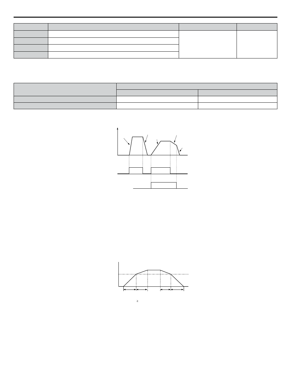
shows an operation example for changing accel/decel. times. The example below requires that the stopping method
be set for “Ramp to stop” (b1-03 = 0).
Output
frequency
Accel Time 1
(C1-01)
Decel Time 1
(C1-02)
Accel Time 2
(C1-03)
Decel Time 2
(C1-04)
Decel Time 1
(C1-02)
FWD (REV)
Run command
ON
OFF
ON
ON
Accel/Decel Time Selection 1
(Terminals S1 to S7, H1- = “7”)
Figure 4.19 Timing Diagram of Accel/Decel Time Change
Switching Accel/Decel Times by a Frequency Level
The drive can switch between different acceleration and deceleration times automatically. The drive will switch from accel/
decel time 2 in C1-03 and C1-04 to the default accel/decel time in C1-01 and C1-02 when the output frequency exceeds the
frequency level set in parameter C1-11. When the frequency falls below this level, the accel/decel times are switched back.
shows an operation example.
Note:
Acceleration and deceleration times selected by digital inputs have priority over the automatic switching by the frequency level set to C1-11.
For example, if accel/decel time 2 is selected, the drive will use only accel/decel time 2; it will not switch from accel/decel time 2 to the
selected time.
Output Frequency
C1-11
Accel/Decel Time
Switch Frequency
C1-03
setting
When the output frequency C1-11, drive uses Accel/Decel Time 1 (C1-01, -02)
When the output frequency < C1-11, drive uses Accel/Decel Time 2 (C1-03, -04)
C1-01
setting
C1-02
setting
C1-04
setting
Figure 4.20 Accel/Decel Time Switching Frequency
n
C6-02: Carrier Frequency Selection
Sets the switching frequency of the drive output transistors. Changes to the switching frequency lower audible noise and reduce
leakage current.
Note:
Increasing the carrier frequency above the default value automatically lowers the drive current rating.
4.7 Basic Drive Setup Adjustments
126
YASKAWA ELECTRIC TOEP YAIZ1U 03A YASKAWA AC Drive – Z1000 User Manual