Refer to, For details on using this function – Yaskawa Z1000 AC Drive HVAC User Manual
Page 164
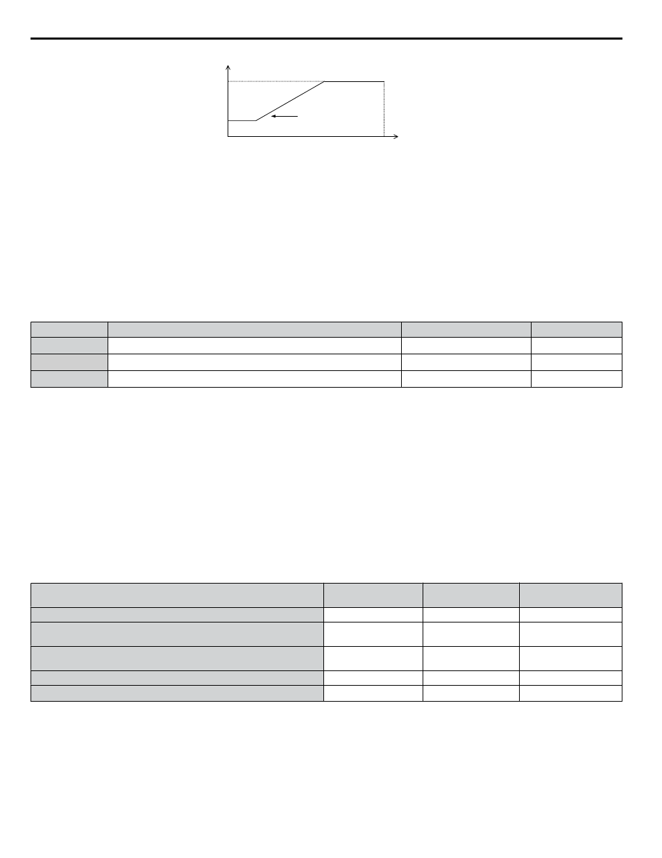
C6-03
C6-04
E1-04
x C6-05
Output Frequency
Output
Frequency
Max Output Frequency
Carrier Frequency
Figure 4.31 Carrier Frequency Changes Relative to Output Frequency
Note:
When C6-05 is set lower than 7, C6-04 is disabled and the carrier frequency will be fixed to the value set in C6-03.
n
d1-01 to d1-04, d1-16, and d1-17: Frequency References 1 to 4, 16, and Jog Frequency
Reference
The drive lets the user switch between up to 5 preset frequency references during run (including the Jog reference) through
the digital input terminals. The drive uses the acceleration and deceleration times that have been selected when switching
between each frequency reference.
The Jog frequency overrides all other frequency references and must be selected by a separate digital input.
The multi-speed references 1 and 2 can be provided by analog inputs.
No.
Parameter Name
Setting Range
Default
d1-01 to d1-04
Frequency Reference 1 to 4
0.00 to 240.00 Hz
<1>
<2>
0.00 Hz
<2>
d1-16
Frequency Reference 16
0.00 to 240.00 Hz
<1>
<2>
0.00 Hz
<2>
d1-17
Jog Frequency Reference
0.00 to 240.00 Hz
<1>
<2>
6.00 Hz
<2>
<1> The upper limit is determined by the maximum output frequency (E1-04) and upper limit for the frequency reference (d2-01).
<2> Setting units are determined by parameter o1-03. The default is “Hz” (o1-03 = 0).
Multi-Step Speed Selection
To use several speed references for a multi-step speed sequence, set the H1- parameters to 3 and 4. To assign the Jog
reference to a digital input, set H1- to 6.
Notes on using analog inputs as Multi-Speed 1 and 2:
• The first frequency reference (Multi-Speed 1) comes from the source specified in b1-01. When using an analog input terminal
to supply the frequency reference, assign the frequency reference source to the control terminals (b1-01 = 1).
• When an analog input is set to “Auxiliary frequency 1” (H3-02 or H2-06 = 2), the value set to this input will be used as the
Multi-Step Speed 2 instead of the value set to parameter d1-02. If no analog inputs are set for “Auxiliary frequency 1”, then
d1-02 becomes the reference for Multi-Step Speed 2.
Select the different speed references as shown in
illustrates the multi-step speed selection.
Table 4.24 Multi-Step Speed Reference and Terminal Switch Combinations
Reference
Multi-Step Speed
H1- = 3
Multi-Step Speed 2
H1- = 4
Jog Reference
H1- = 6
Frequency Reference 1 (set in b1-01)
OFF
OFF
OFF
Frequency Reference 2
(d1-02 or input terminal A1, A2)
ON
OFF
OFF
Frequency Reference 3
(d1-03 or input terminal A1, A2)
OFF
ON
OFF
Frequency Reference 4 (d1-04)
ON
ON
OFF
Jog Frequency Reference (d1-17)
<1>
−
−
ON
<1> The Jog frequency overrides all other frequency references.
4.13 Advanced Drive Setup Adjustments
164
YASKAWA ELECTRIC TOEP YAIZ1U 03A YASKAWA AC Drive – Z1000 User Manual