Terminal configuration, Wire size and torque specifications, 9 control circuit wiring – Yaskawa Z1000 AC Drive HVAC User Manual
Page 88
u
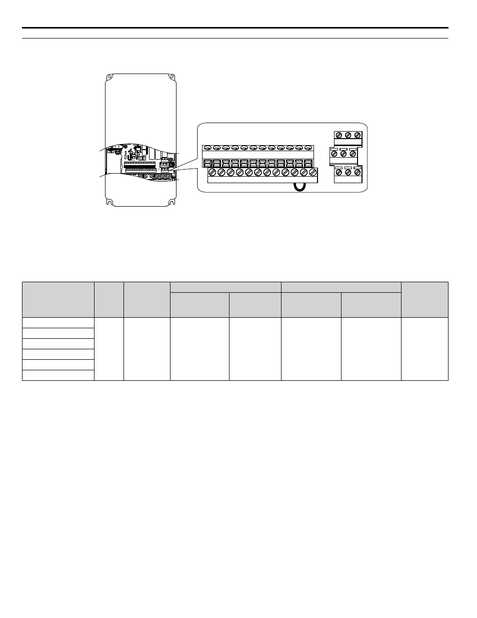
Terminal Configuration
The control circuit terminals are arranged as shown in
IG R+ R- S+ S- +V AC A1 A2 FM AM AC
FE S1 S2 S3 S4 S5 S6 S7 SN SC SP +P
M3 M4 M6
M1 M2 M5
MA MB MC
IG R+ R- S+ S- +V AC A1 A2 FM AM AC
FE S1 S2 S3 S4 S5 S6 S7 SN SC SP +P
M3 M4 M6
M1 M2 M5
MA MB MC
Figure 3.21 Control Circuit Terminal Arrangement
n
Wire Size and Torque Specifications
Select appropriate wire type and gauges from
. For simpler and more reliable wiring, use crimp ferrules on the wire
for ferrule terminal types and sizes.
Table 3.7 Wire Gauges
Terminal
Screw
Size
Tightening
Torque
N
•m
(lb. in)
Bare Wire Terminal
Ferrule-Type Terminal
Wire Type
Recomm.
wire size
mm
2
(AWG)
Applicable
wire size
mm
2
(AWG)
Recomm.
wire size
mm
2
(AWG)
Applicable
wire size
mm
2
(AWG)
S1-S7, SC, SN, SP
M3
0.5 to 0.6
(4.4 to 5.3)
0.75 (18)
Stranded wire:
0.2 to 1.0
(24 to 16)
Solid wire:
0.2 to 1.5
(24 to 16)
0.5 (20)
0.25 to 0.5
(24 to 20)
Shielded wire,
etc.
V+, A1, A2, AC
MA, MB, MC
M1-M6
FM, AM, AC
R+, R-, S+, S-, IG
3.9 Control Circuit Wiring
88
YASKAWA ELECTRIC TOEP YAIZ1U 03A YASKAWA AC Drive – Z1000 User Manual