B2-02: dc injection braking current, B2-03: dc injection braking time at start, B2-04: dc injection braking time at stop – Yaskawa Z1000 AC Drive HVAC User Manual
Page 152
The function triggered by parameter b2-01 depends on the control mode that has been selected.
V/f (A1-02 = 0)
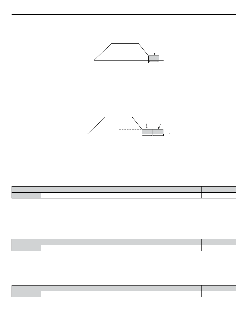
For these control modes, parameter b2-01 sets the starting frequency for DC Injection Braking at Stop. When the output
frequency falls below the setting of b2-01, DC Injection Braking is enabled for the time set in parameter b2-04.
Output
frequency
Time
b2-04
DC Injection
Braking
E1-09 Min. Frequency
b2-01 Zero Speed Level
Figure 4.28 DC Injection Braking at Stop for V/f
Note:
If b2-01 is set to a smaller value than parameter E1-09 (minimum frequency), then DC Injection Braking will begin as soon as the frequency
falls to the value set to E1-09.
OLV/PM (A1-02 = 5)
For these control modes, parameter b2-01 sets the starting frequency for Short-Circuit Braking at stop. When the output
frequency falls below the setting of b2-01, Short-Circuit Braking is enabled for the time set in parameter b2-13. If DC Injection
Braking time is enabled at stop, then DC Injection Braking is performed for the time set in b2-04 after Short-Circuit Braking
is complete.
Output
frequency
Time
DC Injection
Braking
b2-04
b2-13
Short Circuit
Braking
E1-09 Min. Frequency
b2-01 Zero Speed Level
Figure 4.29 Short-Circuit Braking at Stop in OLV/PM
Note:
If b2-01 is set to a smaller value than parameter E1-09 (minimum frequency), then DC Injection Braking will begin as soon as the frequency
falls to the value set to E1-09.
n
b2-02: DC Injection Braking Current
Sets the DC Injection Braking current as a percentage of the drive rated current. The carrier frequency is automatically reduced
to 1 kHz when this parameter is set to more than 50%.
No.
Name
Setting Range
Default
b2-02
DC Injection Braking Current
0 to 100%
50%
The level of DC Injection Braking current affects the strength of the magnetic field attempting to lock the motor shaft.
Increasing the current level will increase the amount of heat generated by the motor windings. Do not set this parameter higher
than the level necessary to hold the motor shaft.
n
b2-03: DC Injection Braking Time at Start
Sets the time of DC Injection Braking at start. Used to stop a coasting motor before restarting it or to apply braking torque at
start. Disabled when set to 0.00 s.
No.
Name
Setting Range
Default
b2-03
DC Injection Braking Time at Start
0.00 to 10.00 s
0.00 s
Note:
Before starting an uncontrolled rotating motor (e.g., a fan motor driven by windmill effect), use DC Injection or Speed Search to stop the
motor or detect motor speed before starting it. Otherwise, motor stalling and other faults can occur.
n
b2-04: DC Injection Braking Time at Stop
Sets the time of DC Injection Braking at stop. Used to completely stop a motor with high inertia load after ramp down. Increase
the value if the motor still coasts by inertia after it should have stopped. Disabled when set to 0.00 s.
No.
Name
Setting Range
Default
b2-04
DC Injection Braking Time at Stop
0.00 to 10.00 s
0.00 s
4.13 Advanced Drive Setup Adjustments
152
YASKAWA ELECTRIC TOEP YAIZ1U 03A YASKAWA AC Drive – Z1000 User Manual