4 option installation – Yaskawa Z1000 AC Drive HVAC User Manual
Page 242
NS MS
K
L
F
M
TX RX
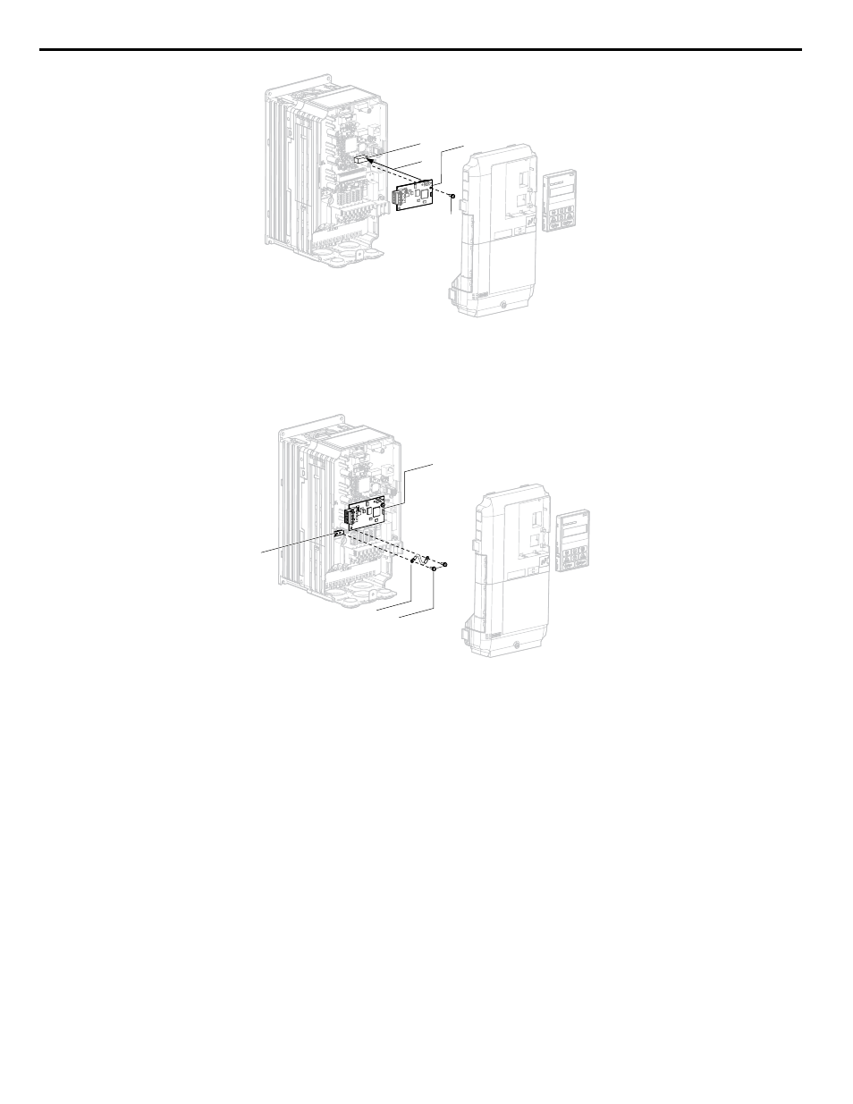
Figure 6.5 Insert the Option
2.
Connect the ground wire (G) to the ground terminal (H) using one of the remaining provided screws (F). Connect the
other end of the ground wire (G) to the remaining ground terminal and installation hole on the option (M) using the
last remaining provided screw (F) and tighten both screws to 0.5 ~ 0.6 N m or (4.4 ~ 5.3 in lbs).
NS MS
F
G
M
H
TX RX
Figure 6.6 Connect the Ground Wire
Note:
There are two screw holes on the drive for use as ground terminals. When connecting three options, two ground wires will need
to share the same drive ground terminal.
Wiring the Option
1.
Route the option wiring.
Depending on the drive model, some drives may require routing the wiring through the side of the front cover to the
outside to provide adequate space for the wiring. In these cases, using diagonal cutting pliers, cut out the perforated
openings on the left side of the drive front cover. Sharp edges along the cut out should be smoothed down with a file
or sand paper to prevent any damage to the wires.
When installing option cards to models 5A0003 to 5A0011, it may be necessary to route the cables connected to the
option through the top cover to the outside. Models 5A0017 to 5A0242 have enough space to keep all wiring inside
the unit.
2.
Connect the communication cables to the option terminal block (TB1).
Note:
Separate the communications cables from the main circuit cables and other wiring and power cables. Use properly grounded
shielded cables for the communication cables to prevent problems caused by electrical interference.
Replacing the Drive Covers and HOA Keypad
1.
Replace and secure the front covers of the drive (A, D) and replace the HOA keypad (B).
6.4 Option Installation
242
YASKAWA ELECTRIC TOEP YAIZ1U 03A YASKAWA AC Drive – Z1000 User Manual