Output terminals, Serial communication terminals – Yaskawa Z1000 AC Drive HVAC User Manual
Page 87
n
Output Terminals
lists the output terminals on the drive. Text in parenthesis indicates the default setting for each multi-function output.
Table 3.5 Control Circuit Output Terminals
Type
No.
Terminal Name (Function)
Function (Signal Level) Default Setting
Page
Fault Relay
Output
MA
N.O. output (Fault)
30 Vdc, 10 mA to 1 A; 250 Vac, 10 mA to 1 A
Minimum load: 5 Vdc, 10 mA
MB
N.C. output (Fault)
MC
Fault output common
Multi-Function
Digital Output
<1>
M1
Multi-function digital output (During run)
30 Vdc, 10 mA to 1 A; 250 Vac, 10 mA to 1 A
Minimum load: 5 Vdc, 10 mA
M2
M3
Multi-function digital output (Zero speed)
M4
M5
Multi-function digital output (Speed Agree 1)
M6
Monitor
Output
FM
Analog monitor output 1 (Output frequency)
0 to 10 V / 0 to 100%
4 to 20 mA / 0 to 100%
Voltage or current output must be selected by Jumper S5 and
H4-07 for FM and H4-08 for AM.
AM
Analog monitor output 2 (Output current)
AC
Monitor common
0 V
–
External Power
Supply
+P
External Power Supply
24 V (Max. 150 mA)
–
<1> Refrain from assigning functions to digital relay outputs that involve frequent switching, as doing so may shorten relay performance life. Switching
life is estimated at 200,000 times (assumes 1 A, resistive load).
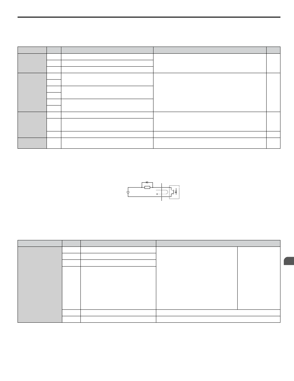
Connect a suppression diode as shown in
when driving a reactive load such as a relay coil. Ensure the diode rating
is greater than the circuit voltage.
A
B
C
D
A – External power, 48 V max.
B – Suppression diode
C – Coil
D – 50 mA or less
Figure 3.20 Connecting a Suppression Diode
n
Serial Communication Terminals
Table 3.6 Control Circuit Terminals: Serial Communications
Type
No.
Signal Name
Function (Signal Level)
Serial Communication
(APOGEE FLN,
BACnet, MEMOBUS/
Modbus, or Metasys
N2)
<1>
R+
Communications input (+)
APOGEE FLN, BACnet, MEMOBUS/
Modbus, or Metasys N2 communication: Use
an RS-422 or RS-485 cable to connect the
drive.
• APOGEE FLN
Comm. RS-422/
RS-485, 4.8 kbps
• BACnet Comm.
RS-485, max. 76.8
kbps
• MEMOBUS/
Modbus Comm.
RS-422/RS-485,
max. 115.2 kbps
• Metasys N2 Comm.
RS-422/RS-485, 9.6
kbps
R-
Communications input (-)
S+
Communications output (+)
S-
Communications output (-)
IG
Communications ground
0 V
FE
Option card ground
–
<1> Enable the termination resistor in the last drive in an APOGEE FLN, BACnet, MEMOBUS/Modbus, or Metasys N2 network by setting DIP switch
S2 to the ON position.
Refer to Control I/O Connections on page 92
for more information on the termination resistor.
3.9 Control Circuit Wiring
YASKAWA ELECTRIC TOEP YAIZ1U 03A YASKAWA AC Drive – Z1000 User Manual
87
3
Electrical Installation