Main circuit wire gauges and tightening torque, Three-phase 600 v class, 8 main circuit wiring – Yaskawa Z1000 AC Drive HVAC User Manual
Page 81
u
Main Circuit Wire Gauges and Tightening Torque
Use the tables in this section to select the appropriate wires and crimp terminals.
Gauges listed in the tables are for use in the United States.
Note:
1. Wire gauge recommendations based on drive continuous current ratings (ND) using 75 °C 600 Vac vinyl-sheathed wire assuming ambient
temperature within 40 °C and wiring distance less than 100 m.
2. Terminals
⊕1, ⊕2, ⊕3, ⊖, B1 and B2 are for connecting optional power devices. Use caution to connect only approved devices to the
correct terminal(s).
• Consider the amount of voltage drop when selecting wire gauges. Increase the wire gauge when the voltage drop is greater
than 2% of motor rated voltage. Ensure the wire gauge is suitable for the terminal block. Use the following formula to
calculate the amount of voltage drop:
Line drop voltage (V) = 3 × wire resistance (Ω/km) × wire length (m) × current (A) × 10
-3
• Refer to instruction manual TOBP C720600 00 for braking transistor option or braking resistor option wire gauges.
• Use terminals
⊕1 and ⊖ when connecting a regenerative converter or a regen unit.
NOTICE: Do not connect a braking resistor to terminals
⊕1 or ⊖. Failure to comply may cause damage to the drive circuitry.
• Use terminals B1 and
⊖ when installing a CDBR-type braking unit on drives with built-in braking transistors (models
5A0003 to 5A0052).
NOTICE: Do not connect a braking resistor to terminals
⊕1 or ⊖. Failure to comply may cause damage to the drive circuitry.
•
Refer to UL Standards Compliance on page 344
for information on UL compliance.
Yaskawa recommends using closed-loop crimp terminals on all drive models. Use only the tools recommended by the terminal
manufacturer for crimping.
Refer to Closed-Loop Crimp Terminal Size on page 347
for closed-loop crimp terminal
recommendations.
The wire gauges listed below are Yaskawa recommendations. Refer to local codes for proper wire gauge selections.
n
Three-Phase 600 V Class
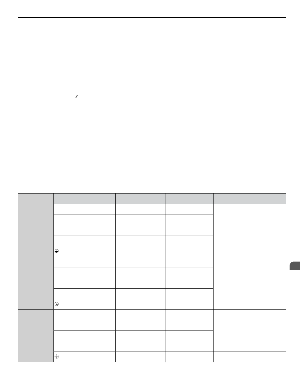
Table 3.2 Wire Gauge and Torque Specifications (Three-Phase 600 V Class)
Drive Model
Terminal
Recomm. Gauge
mm
2
(AWG, kcmil)
Wire Range
mm
2
(AWG, kcmil)
Screw
Size
Tightening Torque
N·m (lb.in.)
5A0003
5A0004
5A0006
R/L1, S/L2, T/L3
2.5
(14)
2.5 to 6.0
(14 to 10)
M4
1.2 to 1.5
(10.6 to 13.3)
U/T1, V/T2, W/T3
2.5
(14)
2.5 to 6.0
(14 to 10)
⊖, ⊕1, ⊕2
–
2.5 to 6.0
(14 to 10)
B1, B2
–
2.5 to 6.0
(14 to 10)
6.0
(10)
2.5 to 6.0
(14 to 10)
5A0009
R/L1, S/L2, T/L3
2.5
(14)
2.5 to 6.0
(14 to 10)
M4
1.2 to 1.5
(10.6 to 13.3)
U/T1, V/T2, W/T3
2.5
(14)
2.5 to 6.0
(14 to 10)
⊖, ⊕1, ⊕2
–
2.5 to 6.0
(14 to 10)
B1, B2
–
2.5 to 6.0
(14 to 10)
6.0
(10)
4.0 to 6.0
(12 to 10)
5A0011
R/L1, S/L2, T/L3
6.0
(10)
2.5 to 16
(14 to 6)
M4
2.1 to 2.3
(18.6 to 20.4)
U/T1, V/T2, W/T3
2.5
(14)
2.5 to 16
(14 to 6)
⊖, ⊕1, ⊕2
–
2.5 to 16
(14 to 6)
B1, B2
–
2.5 to 6.0
(14 to 10)
10
(8)
4.0 to 6.0
(12 to 8)
M5
2.0 to 2.5
(17.7 to 22.1)
3.8 Main Circuit Wiring
YASKAWA ELECTRIC TOEP YAIZ1U 03A YASKAWA AC Drive – Z1000 User Manual
81
3
Electrical Installation