Manually connecting corrector nodes – Blackmagic Design DaVinci Resolve Advanced Panel User Manual
Page 200
COLOR
200
• Using the DaVinci Resolve control surface, select any node, and press the DEL-
CURRENT button (on the T-bar panel).
After you’ve deleted a node, the node to the left and right of the node you deleted are automatically
connected together so that the node tree is unbroken.
Manually Connecting Corrector Nodes
Every serial and parallel node you add is a “Corrector” node, which is capable of either primary or
secondary correction, depending on whether or not you enable the Qualifier/Window/Matte controls.
As a result, each Corrector node has two inputs and two outputs, which lets you separately manage the
RGB image channel, and the Key channel (Alpha or Matte). Here’s an explanation of the components of
a basic node tree, and how they fit together.
The Source:
The source is the clip as processed by the PTZR and Source decode settings,
ungraded. It’s represented by the blue bar to the center left of the node graph. The
Source bar outputs RGB data, and is connected to the RGB input of the first node
in your tree. You can connect the Source bar to more then one corrector node,
creating multiple simultaneous streams of image processing that you can eventually
recombine in different ways using the Parallel or Layer mixer nodes.
RGB Inputs and Outputs:
The yellow dots at the upper right and left of each node are used to connect the
RGB image output from one node to the RGB input of the next node. For a corrector
node to have an effect, you must connect both its RGB Input and its RGB output to
neighboring nodes in the tree.
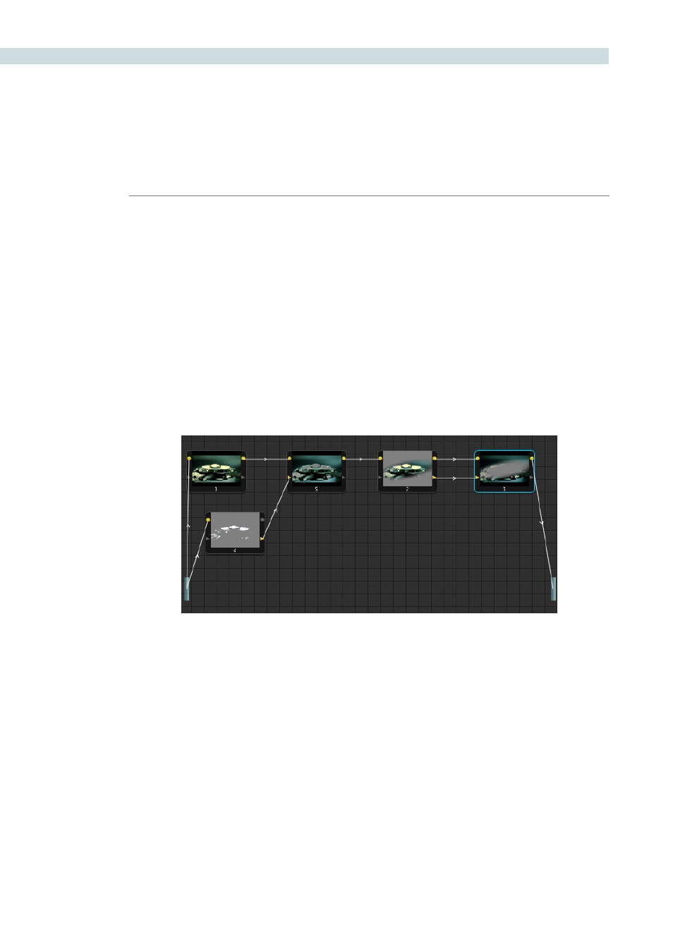
An example node tree with both image and matte processing. The RGB Outputs and inputs of nodes 1, 5, 2, and 3
are connected in serial. Node 4 is feeding a Key into node 5, and node 3 is an Outside node with both its Key and
RGB inputs connected to the node before it.