Set up an sd-sdi, hd-sdi, or component system – Adobe Premiere Pro CC v.7.xx User Manual
Page 95
2. Connect the camcorder or VTR to the television monitor with an S-Video or RCA video cable and RCA audio cables, or an HDMI cable.
3. Set the camcorder or VTR to VTR or Play mode.
4. (For HDV camcorders or VTRs only) Make sure the device is in DV playback mode for DV projects, or HDV playback mode for HDV
projects. See the user manual for your device for details.
Set up an SD-SDI, HD-SDI, or component system
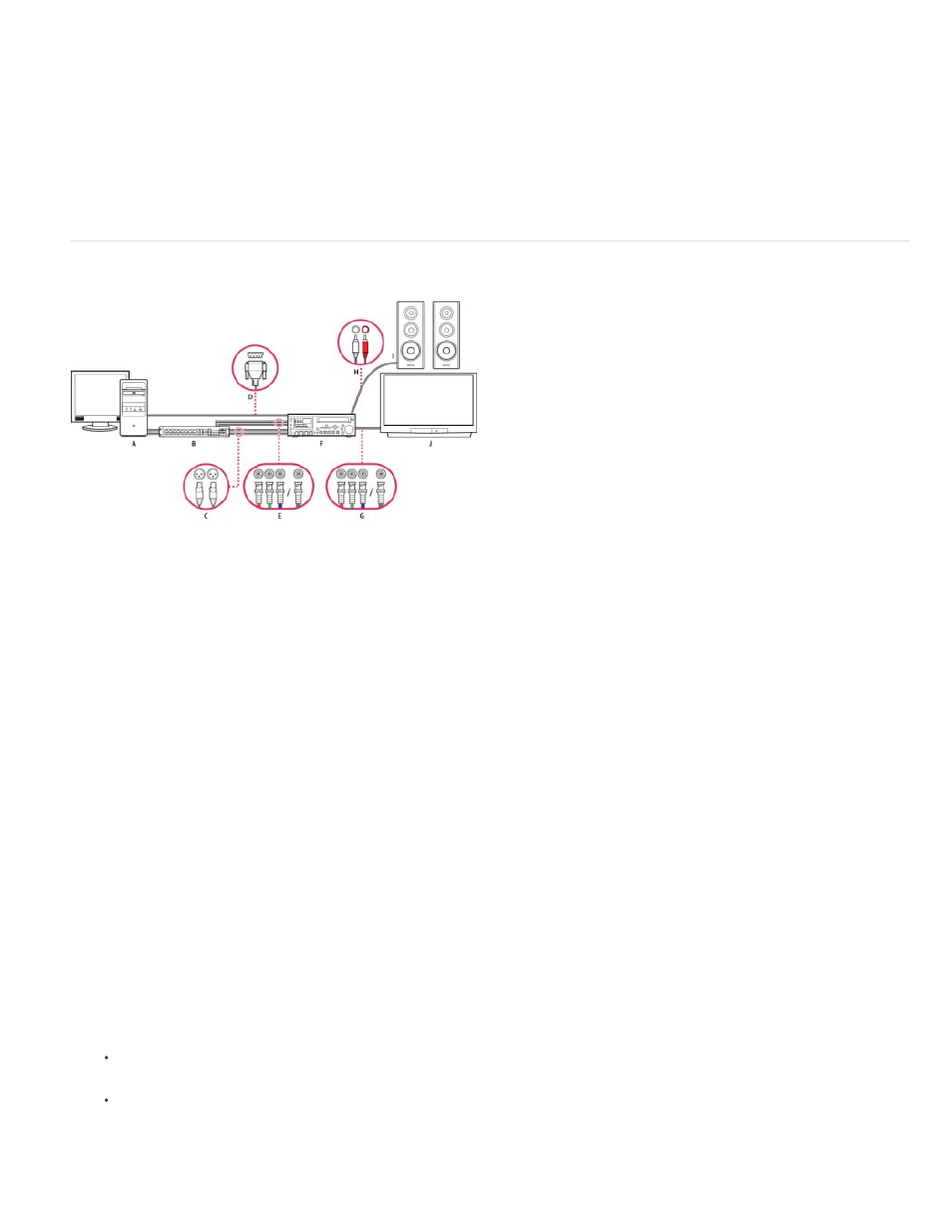
SDI/component setup with breakout box
A. Computer and computer monitor B. (Optional) A/V breakout box C. XLR jacks and plugs for L & R audio D. RS232/422 port and connector E.
BNC jacks and plugs for Y/Pb/Pr component video, BNC jack, and plug for SDI video F. HD/SD VTR G. BNC jacks and plugs for Y/Pb/Pr
component video, BNC jack, and plug for SDI video H. RCA jacks and plugs for L (white) & R (red) audio I. Speakers J. Television monitor
With this setup you can capture audio and video from an SD-SDI, HD-SDI, or component video device (camcorder or VTR). You can monitor the
signal on a TV monitor while editing. Finally, you can export any sequence back to the camcorder or VTR.
This setup requires either an SDI or component PCI card installed in the computer. Alternatively, it requires an external SDI or component device
connected to the computer via FireWire. Either an internal card or an external device would provide ports, usually with BNC connectors, capable of
receiving SDI or component video signals.
Some SDI and component PCI cards come with breakout boxes which provide ports for the SDI or component signals. Some breakout boxes also
provide ports for genlock. Others provide the necessary outputs directly on the card.
1. Connect the SD-SDI, HD-SDI, or component device to the computer or breakout box using SDI or component video cables. A single cable
with BNC connectors carries SDI video, but three separate cables with BNC connectors carry component video signals. Run video cables
from the video outputs of the computer or breakout box to the video inputs of the device. Also run video cables from the video outputs of the
device to the video inputs of the computer or breakout box.
2. Connect the SD-SDI, HD-SDI, or component device to the computer or breakout box using XLR audio cables. Run audio cables from the
audio outputs of the computer or breakout box to the audio inputs of the device. Also run audio cables from the audio outputs of the device
to the audio inputs of the computer or breakout box.
3. Do one of the following:
Connect the serial device control port (RS-422 or RS-232) on the camcorder or VTR with the serial port (Windows) or USB port (Mac
OS) on the computer. Use the Pipeline Digital ProVTR cable for RS-232/422-controlled devices.
If your system has a breakout box with a serial device control port (RS-422 or RS-232), connect the serial device control port on the
device with this port on the breakout box. Do not connect the serial control port on the device with the serial or USB port on the
computer. Some breakout boxes require a standard serial 9-pin D-Sub cable instead of the Pipeline Digital ProVTR cable. Consult the
documentation from the manufacturer of the breakout box.
98