Wcc3.exe screen descriptions, Ea driver screen, Control output ea driver screen – WattMaster WM-WCC3-TGD-01B User Manual
Page 168
WCC3.EXE SCREEN DESCRIPTIONS
WCC III Technical Guide
3-54
Satellite #:_____
Specifi es the number of the satellite you are currently editing. If
you would like to edit a different satellite, use the arrow keys to
move the cursor to this fi eld, enter the desired satellite number, and
press
<Enter>
. 1 to 240.
Control Output _____
This “fi eld” actually contains two separate fi elds. The fi rst fi eld
specifi es the point “type” (i.e., analog input, control output, analog
output, etc.) and displays the current type in textual form. Because
this is a “choice” fi eld, the list of available choices will be displayed
at the bottom of the screen:
<ANALOG INPUT, CONTROL OUTPUT, ANALOG OUTPUT,
TREND LOGGING, LOGIC SWITCH, BINARY OUTPUT>
You may make your selection by pressing the
<space bar>
until
the desired point type has been selected. If you select a point type
that is different than that currently being displayed, the screen will
be rewritten with the appropriate screen and data.
The second fi eld specifi es the point number to edit. For the Control
Output Screen, this number can range from one to eight. If you
would like to edit a different point, use the arrow keys to move
the cursor to this fi eld, enter the desired point number, and press
<Enter>
.
Mode: __________
Specifi es the mode type of the output contact. Because this is a
“choice” fi eld, the list of available choices will be displayed at the
bottom of the screen:
<Undefi ned, EA Driver, Time Clock, Dual Limit>
Satellite # 1
CONTROL OUTPUT 2
Mode: EA Driver
Description: S1-K2h
COM to H on decreasing control signal
Analog Control by: ////
COM to C on increasing control signal
Schedule Control by: L1
Setpoints
On Schedule:
0 DEG.
Alternate On:
0 Deg F.
Off Schedule:
1 DEG.
Off:
0 Deg F
Local Set:
0 DEG.
Selected by:
////
Dead Band width: +/- 0 DEG.
Reverse Action Selc’d When
//// is OFF
Pulse Band width: +/- 0 DEG.
“ “ Off Time: 0 Minutes
“ “ On Time: 3 Minutes
ACTION DIAGRAM
< COM-H > < ALL > < COM-C >
ON
PULSED OFF
PULSED
ON
Setpoint
Dead Band
Pulse Band width
HOME for menu
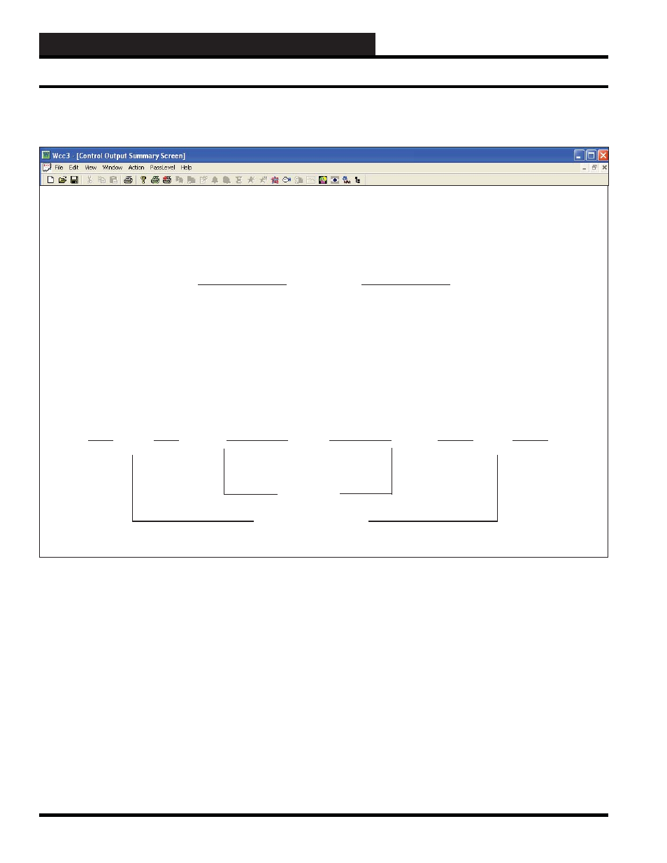
EA DRIVER SCREEN
Control Output Screen’s WCC III Logical Address is XXXKYh or c, where XXX = Satellite Address #, K = Control Output,
Y = Control Output #, h = Heat (General Purpose), and c = Cool (General Purpose)
Control Output EA Driver Screen