Wcc3 v-out relay board sequence, P2 p3 v1 – WattMaster WM-WCC3-TGD-01B User Manual
Page 723
WCC III Technical Guide
16. WCC III V-OUT RELAY BOARD INSTALLATION
16-5
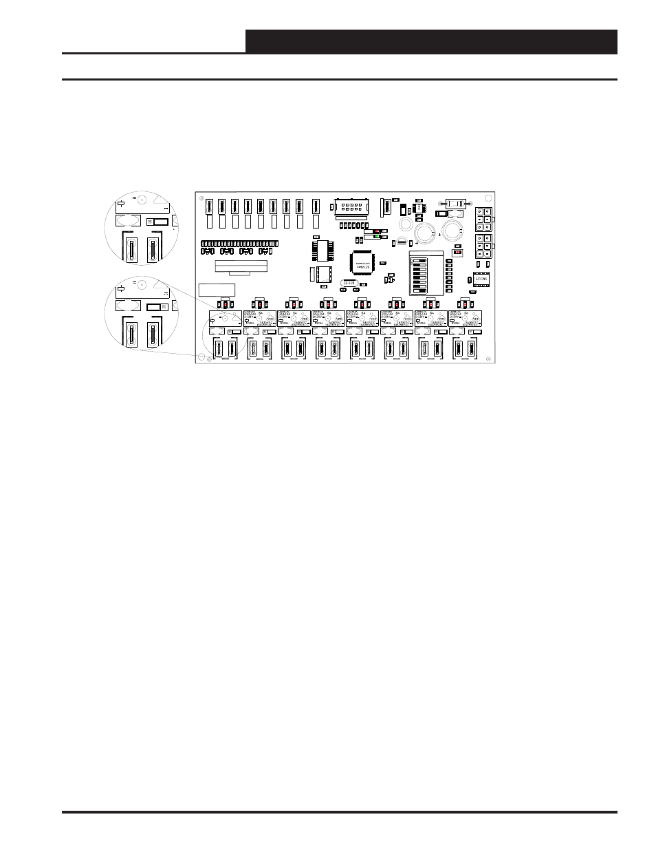
OE430-02 Installation
WCC3 V-Out RELAY board Sequence
There are two modes of operation for the WCC3 V-Out RELAY board. One is the V-Out mode and the other is the Binary Output mode.
Contacts are rated for 1 Amp at 24VAC/VDC operation only. This WCC3 V-Out RELAY board connects to the HSS expansion port on the side of the SAT III controller. The
WCC3 V-Out RELAY board is an expansion board that allows for another 8 binary outputs (Relay Contacts) to be used with the SAT III controller. Up to three of these
WCC3 V-Out RELAY boards may be connected to the SAT III HSS expansion port. Two boards in the Binary Output mode are supported, and one board in the V-Out
These eight Analog Inputs connections must be connected to the eight Analog Outputs of the SAT III controller in the V-Out mode of operation. These analog values are
not digitally transmitted via the HSS port on the SAT III to the WCC3 V-Out RELAY board in the V-Out mode.
There is a load protection device called a varistor across each of the 8 relay output connections of the WCC3 V-Out RELAY board that limit the allowable voltage to no
More than 32 volts AC\DC maximum at 1 amp current draw for each relay output contact. Attempting to switch any voltage greater than 32Volts, or current draws of
more than 1 amp per contact could and will result in damage to the WCC3 V-Out RELAY board and/or to the SAT III controller.
The Dipswitch on the WCC3 V-Out RELAY board Sets the various modes of operation, and dead band in the V-Out mode.
If both MODE (SW1-7 and SW1-8) switches are OFF then the WCC3 V-Out RELAY board is in Binary Output mode. Binary Output 1 to 8 is selected. If MODE 1
Switch (SW1-8) is "ON" then Binary Output 9 to 16 is then selected. If MODE 2 Switch (SW1-7) is "ON" then the V-Out mode is selected. You must cycle power to
The WCC3 V-Out RELAY circuit board after setting dip switch SW1-8. You may select any other switch setting without cycling power to the board.
SW1-1 (1) (V-OUT MODE - ADDS 1 VOLT TO DEAD BAND)
SW1-2 (2) (V-OUT MODE - ADDS 2 VOLTS TO DEAD BAND)
(V-OUT MODE DEFAULT SETTING ON)
SW1-3 (4) (V-OUT MODE - ADDS 4 VOLTS TO DEAD BAND)
SW1-4 (8)
SW1-5 (16)
SW1-6 INVERT (V-OUT MODE) (FLIPS CONDITION OF THE RELAY OUTPUTS)
SW1-7 MODE 2 (V-OUT MODE)
(V-OUT MODE DEFAULT SETTING ON)
SW1-8 MODE 1 (When changing this switch, you must cycle power to the circuit board)
Binary Output Mode of operation
When the WCC V-Out RELAY board is set for the Binary Output mode (SW1- switch # 8 is either "ON" or "OFF" and SW1 - switch #7 is "OFF") the eight relays of the
WCC V-Out RELAY board are controlled by the WCC III program setup of the SAT Binary Output screens for each satellite controller. SW1- switch # 8 “OFF" is
Binary Output board address relays 1 to 8, and SW1- switch # 8 “ON" is Binary Output board address relays 9 to 16. This assumes that SW1 - switch #7 is "OFF".
V-Out Mode of operation (Hysteresis is added to the Setpoint via setting of the SW1 Dipswitch)
When the WCC V-Out RELAY board is set for the V-Out mode (SW1- switch # 7 "ON"), the relay output will turn "ON" when the input voltage rises above 7.5 VDC
"OFF" when the input voltage drops below 7.5 VDC (+/- .25V) minus the dead band setting that is determined by SW1 dipswitch settings. These dipswitch settings apply
for all eight inputs and outputs.
When SW1-1 is selected, 1 volt is added to the dead band. (Dead Band = +/- 1 volts)
When SW1-2 is selected, 2 volts are added to the dead band. (Dead Band = +/- 2 volts)
(DEFAULT)
When SW1-1 and SW1-2 is selected, 3 volts are added to the dead band. (Dead Band = +/- 3 volts)
When SW1-3 is selected, 4 volts are added to the dead band. (Dead Band = +/- 4 volts)
When SW1-3 and SW1-1is selected, 5 volts are added to the dead band. (Dead Band = +/- 5 volts)
wire power and ground pigtail must be provided for connection to 24VAC and GND to power the WCC3 V-Out RELAY board.
1
RLY 8
COM
RLY 7
COM
RLY 6
COM
RLY 5
COM
RLY 4
COM
COM
RLY 3
RLY 8
RLY 7
RLY 6
RLY 5
RLY 4
RLY 3
RLY 2
RLY 1
POWER
COM
CHAS
S
IS
G
N
D
MODE 2
WATTMASTER CONTROLS, INC
PROGRAM SOCKET
MADE IN USA
YS102058 REV3
WCC3 Vout RELAY BOARD
HS
S
HS
S
DRV
485
OPTIONS
16
MODE 1
INVERT
8
4
2
RLY 2
RLY 1
VIN
8
VIN
7
VIN
6
VIN
5
VIN
4
VIN
3
VIN
2
VIN
1
OUT
COM
SERIAL #
R6
6
R6
5
R6
4
R6
3
R6
2
R6
1
R6
0
R5
9
GND
U3
C1
C2
C3
C4
C5
C6
C7
C8
C9
C1
0
C1
1
C1
2
C13
C1
4
C1
5
C1
6
C1
7
C18
C1
9
C20
C21
C22
C2
3
C2
5
D3
D4
D5
D6
D7
STAT
D1
0
D11
COMM
D13
D1
4
D15
D17
L1
P2
P3
P4
P6
P7
P9
P10
P12
P13
P14
P16
P17
P19
P2
0
P21
P23
P40
P28
P29
P30
R1
R2
R3
R4
R5
R6
R7
R8
R9
R10
R11
R12
R13
R1
4
R1
5
R1
6
R1
7
R1
8
R1
9
R2
0
R2
1
R2
2
R2
3
R2
4
R2
5
R2
6
R2
7
R2
8
R2
9
R3
0
R3
1
R3
2
R3
3
R34
R3
5
R36
R3
7
R3
8
R3
9
R4
0
R4
1
R4
2
R4
3
R4
4
R4
5
R4
6
R4
7
R4
8
R4
9
R5
0
R5
1
R5
2
R53
R54
R55
R56
R57
R58
SW1
U1
U2
U4
U6
V1
V2
V3
V4
V5
V6
V8
V9
VR1
X1
K1
K2
K3
K4
K6
K8
K5
SA
5A30VDC
10A250VAC ~
VDE
DC24V
OMRON
G5Q-1A4
CHINA
V7
U
L
N
2802A
EEP
R
O
M
93C46
ENGINEERING
INSTALLATION GUIDE
WCC III V-OUT RELAY BOARD - WITH N/O N/C RELAY CONTACTS
WATTMASTER PART # OE430-02 (SS5008)
NC
NO
RLY 1
P2
P3
V1
5A30VDC
10A250VAC ~
VDE
24V
CHINA
NC
NO
RLY 1
P2
P3
V1
5A30VDC
10A250VAC ~
VDE
24V
CHINA
NC
NO
N.O. JUMPER SELECTED
NORMALLY OPEN
N.C. JUMPER SELECTED
NORMALLY CLOSED
NC
NO
NC
NO
NC
NO
NC
NO
NC
NO
NC
NO
NC
NO
OUT
OUT
OUT
OUT
OUT
OUT
OUT
The WCC3 V-Out RELAY (OE430-02) board has eight relays each with a jumper selectable N.O. (Normally Open) or N.C. (Normally Closed) contacts. These relay
Mode is supported. One HSS expansion board will add 20 VA of VA load to the SAT III power requirement.
The connecting HSS cable is available in 1 ft., 1 / ft , 3 ft., 25 ft., 40 ft., 80., and 120 ft. Lengths.
1
2
.
No more than 150 ft. of total wire can be used to power a SAT III HSS loop.
Dipswitch SW1-7 (MODE 2 - V-Out Mode) and SW1-8 (MODE 1 - Binary Output Mode) selects the MODE of operation for the WCC3 V-Out RELAY board.
(+/-.25V) plus the dead band setting that is determined by Sw1 settings. When the WCC3 V-Out RELAY board is set for the V-Out mode, the relay output will turn
Function. Also, the HSS connector must be connected to the SAT III HSS expansion port for power and ground connections to the SAT III controller or a special two
The eight analog inputs on the WCC3 V-Out RELAY board must be wired to the eight analog outputs on the SAT III or SAT II controller in order for the V-Out mode to