13b. wcc iii - mcd2 installation guide, Lcd display – WattMaster WM-WCC3-TGD-01B User Manual
Page 627
13B. WCC III - MCD2 INSTALLATION GUIDE
WCC III Technical Guide
13B-15
The 4 Line by 20 Character LCD screen
on the WCCIII-MCD2
The CrystalFontz – 4 by 20 line LCD is an end user viewing
interface that is used to show the current status of the WCCIII-
MCD2.
This 4 by 20 line LCD display will currently show the following
options:
•
IP address (Current IP confi guration for eth0 of the
WCCIII-MCD2)
•
System Time (Current time and date of the
WCCIII-MCD2)
•
System Uptime WCCIII-MCD2 Uptime (Time
since last reboot)
•
CPU Load Main processor CPU utilization (User
%, System%, Nice %, and Idle %)
•
NetLoad IP packet processing utilization (RX
(Incoming), and TX (Outgoing) packet processing)
•
POWER ON and POWER OFF status
The four status LEDs to the left of the LCD display the following:
•
Top LED – Labeled “POWER” – Displays the On/
Off/Running condition of the WCCIII-MCD2.
LED stays “RED” during initial power up or when
manually powered down, then turns “YELLOW”
and then “GREEN” during the self-test boot
up sequence. When the SBC and BackTask
are functioning, the LED will turn “GREEN”
to indicate that the WCCIII-MCD2 is fully
functioning.
•
2nd from Top LED – Labeled “BACKTASK” –
This LED displays the On/Off Condition (Running
or not Running) of the Backtask program. If
the LED is RED – the Backtask program is not
running. If the LED is Green – the Backtask
program is running normally.
•
3rd from top LED – Labeled “Network” and
is bi-color. Red LED means no connectivity.
“YELLOW” LED means access to the local Intra-
net has been made. GREEN LED means that
connection to the Internet has been made.
•
Bottom LED – Labeled “EMAIL” – Normal Status
for this LED is to Off, and this LED will turns
Green for fi ve seconds every time an EMAIL is
sent from the WCCIII-MCD2. On initial power up
this LED will turn “YELLOW” then “GREEN”
during the self-test boot up sequence
LCD Display
The CrystalFontz LCD module also used control the ATX (Power
Supply ON/OFF) type functionality of the PCM-9362N SBC
through the “H1” output connector which connects to the back
to inputs on the PCM-9362N SBC through the 50 pin “SBC
INTERNAL I/O CABLE” assembly.
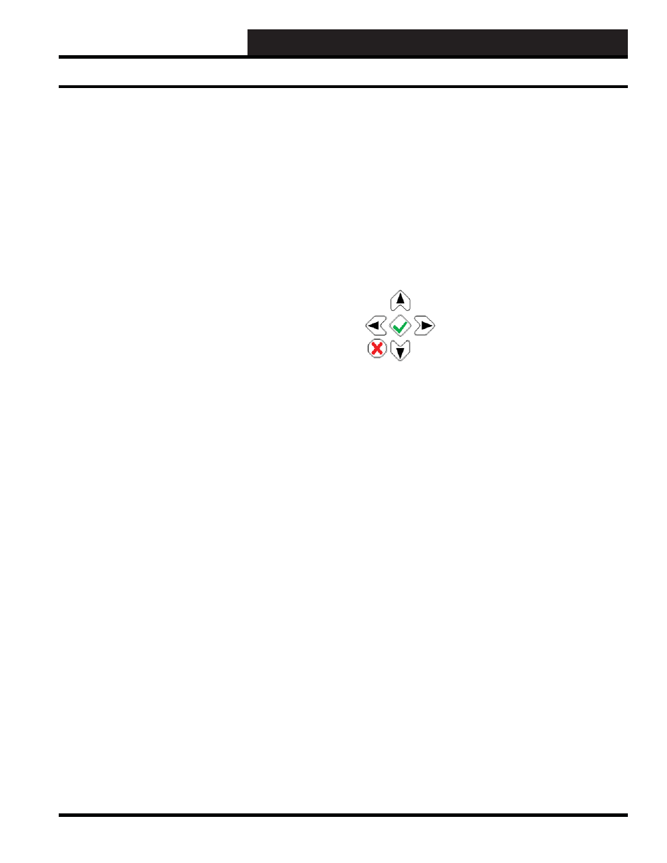
The LCD’s Keypad
The LCD Keypad is used for the LCD screen navigation and to
control startup (power ON), Shutdown (power OFF), and reset of
the WCCIII-MCD2 device.
Starting the WCCIII-MCD2
Press and hold the Green Checkmark button for 1 second. The LCD
display will momentarily display, “Power On” before starting.
The WCCIII-MCD2 will automatically restart upon the application
or resumption of power after a power outage.
Resetting the WCCIII-MCD2
Press and hold the Green Checkmark button for 4 seconds. The
LCD display will momentarily display “Reset” before Reset
occurs.
Shutting Down the WCCIII-MCD2 - Soft Shut Down
Press and hold the Red X button for 4 seconds. The LCD display
will then display, “Power Off” during the Power Off period.
Forced Shut Down of the WCCIII-MCD2 - Hard Shut
Down
Press and hold the Red X button for 8 seconds. The LCD display
will then display, “Power Off” during the Power Off period. Files
are still open.