WattMaster WM-WCC3-TGD-01B User Manual
Page 518
WCC III Technical Guide
12-22
12. WCC III INSTALLATION
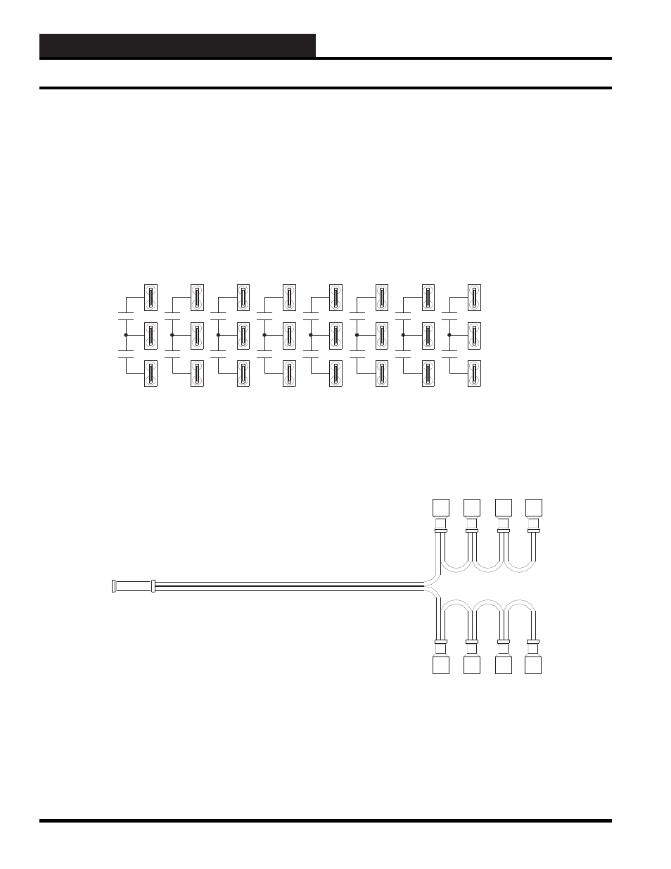
The terminals for the binary outputs are found at the lower left-
hand corner of the SAT III controller and are labeled “H”, “COM”,
and “C”. The relay contact can make or break a 24-VAC or 24-
VDC circuit between the COM to H or COM to C terminals.
The COM to H contacts are referred to as XXXK1h-K8h in the
WCC III point addressing scheme, and the COM to C contacts
are referred to as XXXK1c-K8c in the WCC III point addressing
scheme. XXX is the Satellite address number 1 to 239, “K” stands
for contact, and the numbers 1-8 stand for the channel on the SAT
III controller.
H
COM
C
1
2
3
4
5
6
7
8
1
2
3
4
5
6
7
8
Figure 12-18: SAT III “H” and “C” control output schematic
Each “H” and “C” contact connection has a “COM” connection
associated with it. Please note that each one of the sets of the
corresponding “H” and “C” contacts are also isolated from each
other. The “COM” connection means common. When wiring
the control outputs, typically all of the “COM” connections are
wired together, using the supplied jumper wire (PL100867). This
“COM” common connection can either be connected to 24VAC /
24VDC or GROUND depending on the application.
Figure 12-19: A control output common jumper wire is provided (PL100867) for connecting the eight “COM”
connections together
The pre-made control output common jumper wire is provided
in the initial spare parts kit that came with the SAT III controller.
This spare parts kit contains various input load resistor packs,
spare fuse, and the control output common jumper. The spare parts
kit is WattMaster part number PL102029.
SAT III Relay Outputs