Wcc iii installation, Sat iii analog inputs, Wcc iii technical guide 12-42 – WattMaster WM-WCC3-TGD-01B User Manual
Page 538
WCC III Technical Guide
12-42
12. WCC III INSTALLATION
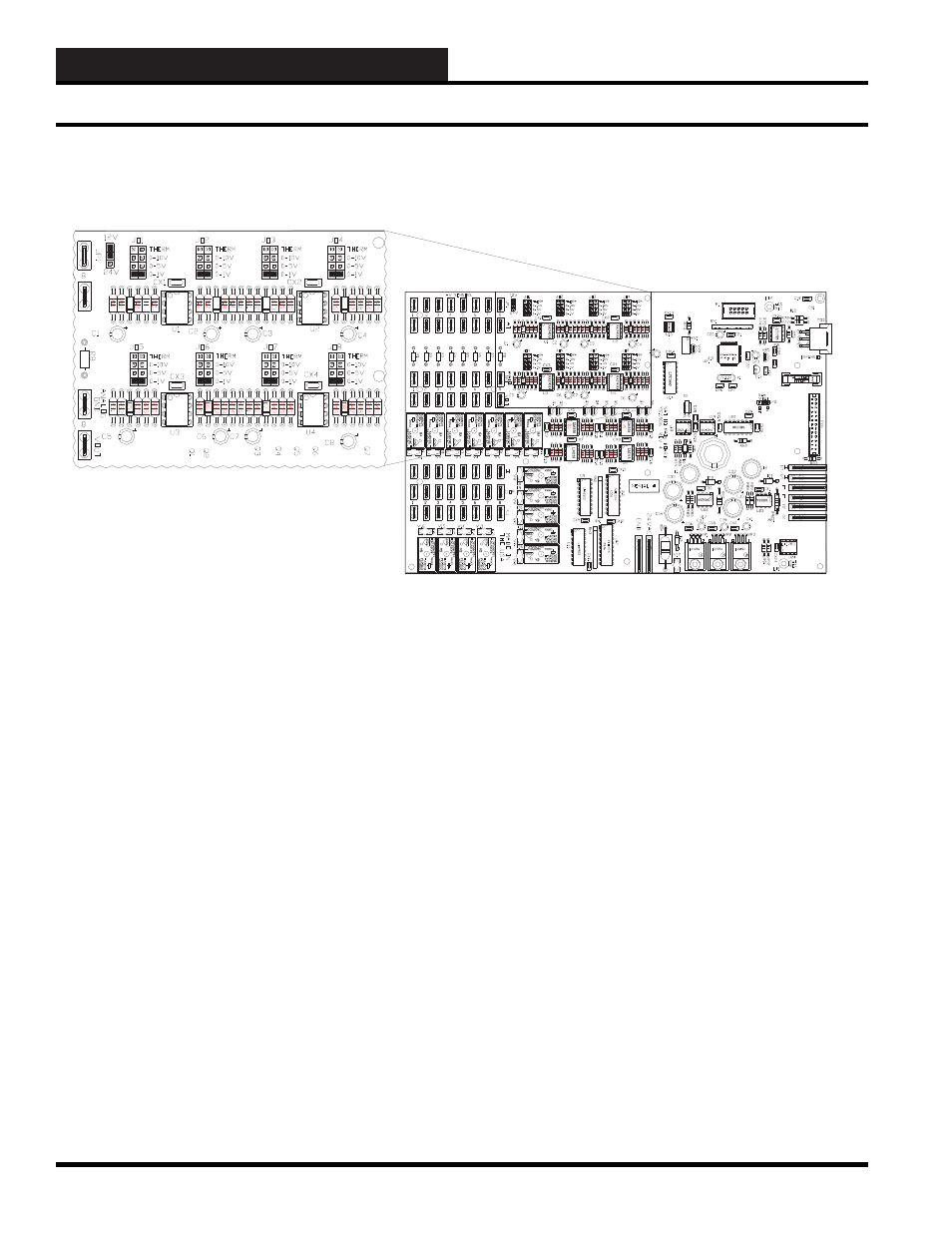
JO1 corresponds to ATI #1 input, JO2 corresponds to ATI #2 input,
JO3 corresponds to ATI #3 input, JO4 corresponds to ATI #4 input,
JO5 corresponds to ATI #5 input, JO6 corresponds to ATI #6 input,
JO7 corresponds to ATI #7 input, JO8 corresponds to ATI #8 input,
while the jumper setting at JP1 sets the voltage for the eighth +V
connection point of the SAT III controller.
OP
A2743
P
A
OP
A2743
P
A
OP
A2743
P
A
OP
A2743
P
A
Zoomed in view of the SAT III mother board circuit board Rev 4
showing location of the Analog input selection jumpers. JO1 to JO8
.
Figure 12-35: SAT III Analog Input Jumper locations (located under the SAT III cover)
SAT III Analog Inputs
This jumper (JP1) can be set to +12VDC, or +24VDC so that
the voltage at the eighth +V connection point is either +12 VDC
or +24 VDC. The +24VDC is useful when connecting 4-to-20
mA sensors that require a power connection voltage greater than
+12VDC. You may connect up to eight 4-to-20 mA sensors to this
eighth +V (+24VDC) connection point. This JP1 jumper is located
under the cover of the SAT III controller, just to the right of the
eighth +V connector.