Wcc3.exe screen descriptions, Logic switch screen, Wcc iii technical guide 3-79 – WattMaster WM-WCC3-TGD-01B User Manual
Page 193: Sat iii, Supplied pc-01 cable
WCC III Technical Guide
3-79
WCC3.EXE SCREEN DESCRIPTIONS
8
7
SAT ADDRESS
2
1
4
8
A 3 WIRE ROOM SENSOR WILL NOT
REQUIRE A LOAD RESISTOR WHEN SET
FOR A 1 VOLT INPUT.
WattMaster Controls Inc.
BINARY
INPUTS
BINARY
INPUTS
L8
ON OFF
128
32
16
64
L4
L3
L2
L1
L6
L5
L7
L11
L12
ON OFF
L10
L9
ON OFF
L15
L16
L14
L13
C
H
4
3
5
6
2
1
LOCAL SET
STATUS 2
STATUS 3
STATUS 1
HSS XMIT
LOCAL SET
LOCAL SET DISABLE
BATT ON/ OFF
PULSE INPUT
OPTION 1
TEST
OPTION 3
OPTION 2
ON OFF
STATUS
HSS REC
SAT XMIT
SAT REC
ANALOG INPUT
JUMPER SELECTION
A 2 WIRE ROOM SENSOR WILL REQUIRE
A 300 OHM LOAD RESISTOR WHEN SET
FOR A 1 VOLT INPUT.
A 4 TO 20 mA SENSOR WILL REQUIRE A
50 OHM LOAD RESISTOR WHEN SET FOR
A 1 VOLT INPUT, OR A 250 OHM LOAD
RESISTOR WHEN SET FOR A 5 VOLT INPUT.
CURRENT
INPUT
THERMISTOR
INPUT
0 - 1V
0 - 5V
0 - 10V
THERM
0 - 1V
0 - 5V
0 - 10V
THERM
0 TO 10V
INPUT
0 TO 5V
INPUT
0 TO 1V
INPUT
0 - 10V
0 - 1V
0 - 5V
0 - 10V
THERM
0 - 1V
0 - 5V
THERM
0 - 1V
0 - 5V
0 - 10V
THERM
PROGRAMMABLE CONTROLLER
SAT III
H
C
COM
CHANNEL
2
1
3 4
2
1
3 4
5 6 7 8
5 6 7 8
V
OUT
GND
L
O
A
D
+V
ATI
A2
50
VA
C
~
5A
30
V
D
C
SA
VDE
G5
Q
-1
A
4
OM
R
O
N
EACH CONTACT
IS RATED FOR
24VAC OR VDC
@ .5 AMP MAX
0-15VDC
OUTPUT
MIN LOAD
IS 1K OHM
RESISTIVE
VDC ONLY
WCC3 BINARY IN W/ TIME DELAY
WATTMASTER CONTROLS, INC
YS102072 REV 2
24
V
24VAC
120VAC
TO OTHER
SAT III OR TO
WCC III - MCD
WIRE "T" TO "T"
"R" TO "R"
"SHD" TO "SHD"
TO OTHER
SAT III OR TO
WCC III - MCD
BUTT SPLICE POWER
OBSERVE POLARITY
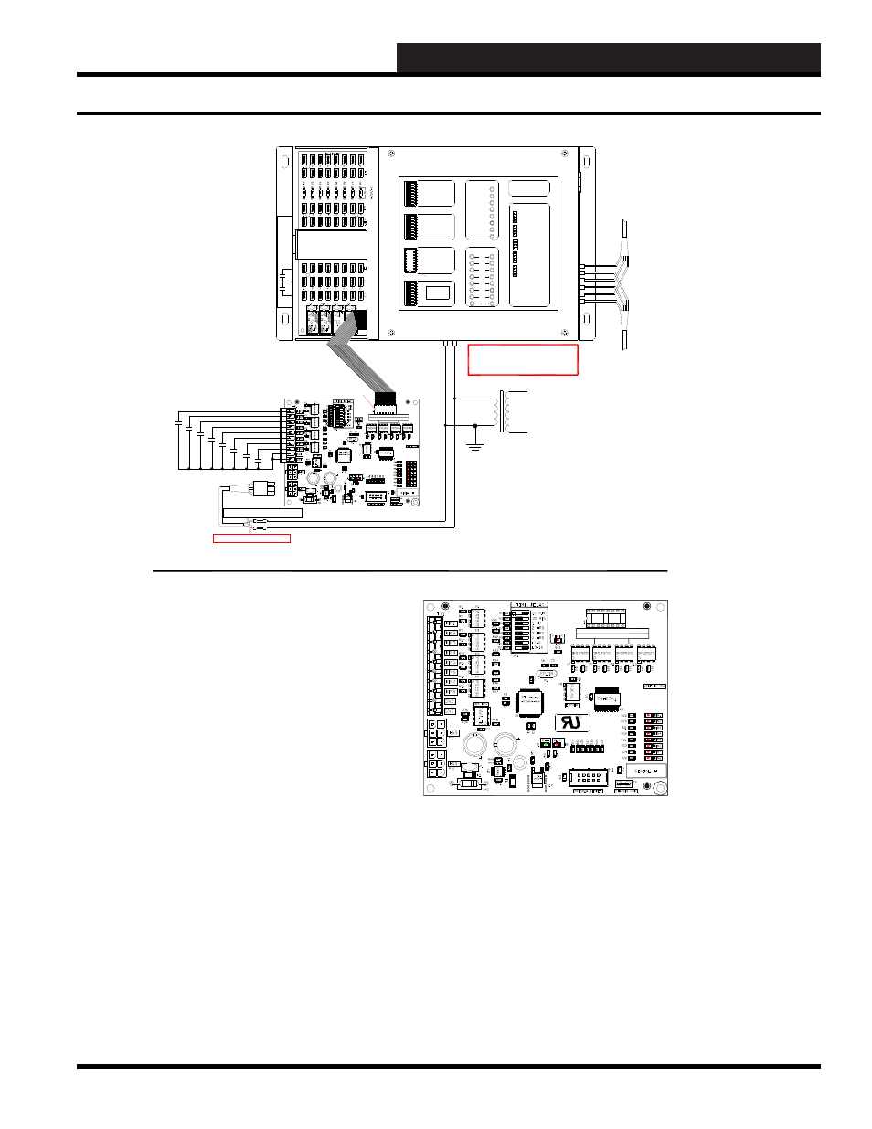
CONNECTION FROM SAT III TO BINARY INPUT BOARD
USING THE "OLD" RIBBON CABLE CONNECTION METHOD
DRY INPUT CONTACTS ONLY
24VAC
GND
TWO BINARY INPUT BOARDS MAY BE WIRED TO
THE SAT III CONTROLLER USING THIS METHOD.
CONNECT THE FIRST ONE TO L1 TO L8 SWITCH
BINARY INPUTS, AND THE SECOND ONE TO L9 TO
L16 SWITCH BINARY INPUTS.
SEE MANUAL FOR DIP
SWITCH SETTINGS
REPLACE THE DIP SWITCH IN
THE SAT III COVER WITH THE
SUPPLIED RIBBON CABLE.
OBSERVE POLARITY
PIN #1
PIN #1
RED WIRE - 24VAC
BROWN WIRE - GND
STRI
PE
IS
PIN
#1
CONTACT CLOSURE TO GND
ONLY
NEW WCC HSS BINARY INPUT WITH TIME DELAY BOARD (YS102072)
The new WCC3 Binary Input /w time delay board provides a terminal point
for landing wire for a external input switch / relay contact. It can interface to
the SAT III controller via a 16 pin ribbon cable with "DIP"
connectors on both sides. Connect "J1" on the Binary Input board to one of
the two removable DIPSWITCHES on the cover of the SAT III controller.
These two switches are labeled Binary Inputs on the cover of the SAT III
controller. Or an alternative method of connection to the SAT III
controller is provided by the 6 pin HSS communications port on the side
of the SAT III controller.
The eight Binary Inputs on the new WCC3 Binary Input /w time delay
board are dry contact closures to ground only.
There is a time delay switch on the new WCC3 Binary Input /w time delay
board. This time delay switch determines how long the input will stay on
after a momentary switch contact is applied to the input of the new WCC3
Binary Input /w time delay Board.
With the time delay dipswitch (1 to 6) all OFF, there is no delay ON for all
eight inputs. Time Delay dipswitch (1 - 15 MIN) ON there is a 15 minute
delay ON for all eight inputs. Time Delay dipswitch (2 - 30 MIN) ON
there is a 30 minute delay ON for all eight inputs. Time Delay dipswitch
(3 - 1 HOUR) ON there is a 1 hour delay ON for all eight inputs. Time Delay
dipswitch (4 - 2 HOUR) ON there is a 2 hour delay ON for all eight inputs.
Time Delay dipswitch (5 - 3 HOUR) ON there is a 3 hour delay ON for all
eight inputs. Time Delay dipswitch (6 - 4 HOUR) ON there is a 4 hour delay
ON for all eight inputs. These Dipswitch settings are additive.
With Time Delay dipswitch (1 - 15 MIN, 2 - 30 MIN, and 3 - 1 HOUR) ON
there is a 1 hour and 45 minute delay ON for all eight inputs.
NOTE:
This Time Delay dipswitch is ignored when the Binary Input w/ time delay board is
connected via the HSS port. There are 16 independant time delays on the Binary Input
screen of the WCC III front end software. One for each of the 16 binary inputs.
The eight input status LEDs on the new WCC3 Binary Input /w time delay board
will not stay lit during a time delay when it is connected to the SAT III via the HSS port.
This Binary Input board power requirements are 24VAC and it draws 5 VA.
The 24VAC power Connection is P2 or P3, and you must observe polarity when
connecting this power connection to the SAT III.
WARNING:
OBSERVE POLARITY
BETWEEN THE SAT III AND THE
BINARY INPUT BOARD - GROUND
CONNECTIONS MUST BE THE SAME.
SUPPLIED
PC-01 CABLE
WCC3 BINARY IN W/ TIME DELAY
WATTMASTER CONTROLS, INC
YS102072 REV 2
C
US
R
120VAC WIRING IS BY OTHERS
THE VA RATING FOR THE SAT III CONTROLLER IS 15VA.
THE VA RATING FOR THE WCC3 BINARY INPUT BOARD (OE431-01) IS 5 VA.
THE VA RATING FOR THE WCC3 V-OUT RELAY BOARD (OE430-01) IS 10 VA.
THE VA RATING FOR THE WCC3 V-OUT RELAY BOARD (OE430-02) IS 20 VA.
Logic Switch Screen