WattMaster WM-WCC3-TGD-01B User Manual
Page 549
12. WCC III INSTALLATION
GUIDE
WCC III Technical Guide
12-53
the word “TEST” into one of the control point values in the TUC/
RTU controller to check the operation of the TUC/RTU controllers
with an alternate setpoint or schedule, then the user could place
the TEST switch in the ON position to make this function work
with out physically having to go back to the front-end computer to
change a setpoint via the computer.
Addressing (Numbering) of the TUC/
RTU Controllers that are Connected
to the SAT 3C
There can be up to a total of eight TUC-5R/5R+/5RX/RTU-
17 controllers connected together on a local TUC RS-485
communication loop to the SAT 3C controller. The software that
is written for each TUC/RTU controller is application specifi c, and
must also be written for use with the WCC III system. In order
for the SAT 3C to communicate properly with each individual
TUC/RTU, each TUC/RTU must be assigned a separate address
(number) from 1 to 8. This addressing or numbering is assigned by
positioning the small dipswitch on each of the TUC/RTU boards
in the proper position. The address switches are housed together in
a block as shown below:
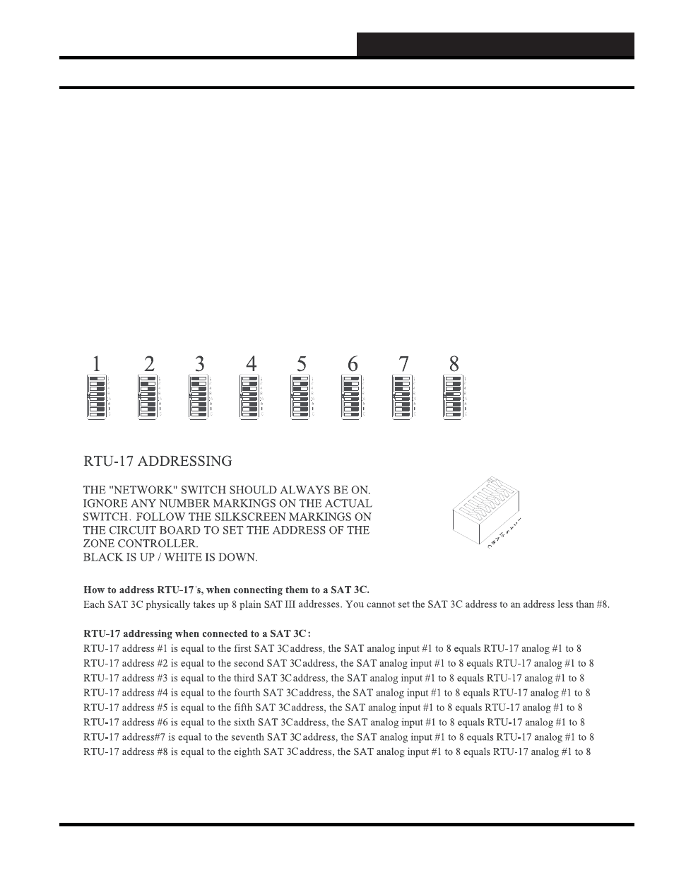
When the switch is in the “On” position, it represents the number
on the right in the drawing below. That is, when switch #3 is “On”
and all of the other switches are “Off,” the TUC is named #4. The
switches are additive. That is to say, when switches 1 and 2 are
“On,” the TUC is named #3.
Figure 12-42: RTU/TUC addressing when connected to a SAT 3C Controller
TUC/RTU Controllers Addressing