Zone controller actuator package wiring, Installation & wiring, Wiring considerations – WattMaster WM-WCC3-TGD-01B User Manual
Page 814: Override alarm
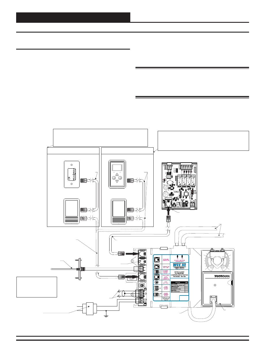
Zone Controller Actuator Package Wiring
1
0
OE282
24 VAC Transformer. Size As
Required For Number Of Controllers
Connected. Each VAV/Zone Controller
Actuator Package Requires 6 VA
Minimum.
Wire To Next VAV/Zone Controller Actuator
Package Or Device On The Local
Communications Loop Using 2 Conductor
Twisted Pair With Shield Cable Available From
WattMaster. All Communication Cable Used
Must Be Belden 82760 Or Its Equivalent.
Line
Voltage
24 VAC
Connector Not
Used With This
Product
Damper Actuator
Damper Actuator Cable
OE210-02, OE211-02, OE212-02
Or OE213-02 Modular Room Sensor
Display
Override
OVERRIDE
ALARM
Note: When Used, The CO Sensor Always Connects To The VAV/Zone
Controller First Using A TSDRSC Cable Of The Appropriate Length. The
Digital Room Sensor Then Connects To The CO Sensor With Another
TSDRSC Cable. The Total Length Of Both Cables Combined Cannot Exceed
120 Feet. If Using Only The Digital Room Sensor Use TSDRSC Cable To
Connect To The VAV/Zone Controller.
2
2
OE217-00
Digital Room Sensor
OE255-01 Or OE256-01
CO Sensor
2
Wiring When Using A Modular Sensor
Wiring When Using A Digital Room Sensor
OE255-01 Or OE256-01
CO Sensor
2
OE325-01 Fan & Reheat Expansion
Module
Connect FRP Tubing (By Others) To Terminal Unit Air
Flow Pickup Tube Hi & Lo Ports
This Expansion Module Is Only Required For Single Duct
Terminal Units With Reheat And All Fan Terminal Units
Modular Expansion Cable
Supplied With OE325-01 Expansion Module
FMRSC Cable
TSDRSC Cable
TSDRSC or FMRSC Cable As
Required. Select Cable
Depending On Sensor(s) Used.
See Notes Above For Details.
Optional - Discharge/Duct Air
Temperature Sensor. Locate
In Ductwork Downstream Of
The Terminal Unit.
Note: When Used, The CO2 Sensor Always Connects To The VAV/Zone
Controller First Using An TSDRSC Cable Of The Appropriate Length. The
Modular Room Sensor Then Connects To The CO2 Sensor With A FMRSC
Cable. The Total Length Of Both Cables Combined Cannot Exceed 120 Feet. If
Using Only The Modular Room Sensor, Use FMRSC Cable To Connect To The
VAV/Zone Controller.
ZONE
EXPA
NSION
YS
10
22
52
R
E
V
1
WATMASTER
CONTRO
LS
INC.
M
A
DE
IN
USA
Rc
R1
R2
R3
R4
AO
U
T
GND
RELAYS
ANALOG
OUTP
U
T
STAT
THERM
4-20mA
0-10V
0-5V
GND
AI
N
ANALOG
INPUT
VREF
EXPANSION IN
PWR
P
IC18
F4520
10A250V
A
C
~
5A
30VD
C
SA
VDE
G5Q-1A4
OMRON
DC24V
CH
IN
A
10A250V
A
C
~
5A
30VD
C
SA
VDE
G5Q-1A4
OMRON
DC24V
CH
IN
A
10A250V
A
C
~
5A
30VD
C
SA
VDE
G5Q-1A4
OMRON
DC24V
CH
IN
A
10A250V
A
C
~
5A
30VD
C
SA
VDE
G5Q-1A4
OMRON
DC24V
CH
IN
A
COMM
TB3
STAT
GND
GND
24VAC
24VAC
R
SHLD
T
TB2
REC
T
SHLD
R
24 VAC
GND
www.orioncontrols.com
OE744-32-VAVZ
P.I. VAV/ZONE
CONTROLLER ACTUATOR
PACKAGE
WattMaster
Label
WARNING: When Multiple
VAV/Zone Controller Actuator
Packages Are Powered From
A Single Transformer Polarity
Must Be Observed Or Damage
To The Controllers Will Result.
Figure 7: VAV/Zone Controller Actuator Package Wiring
Wiring Considerations
The OE325-01 Zone Controller Expansion Module connects to the
VAV/Zone Controller Actuator Package by means of a modular cable
provided with the expansion module. Power is supplied to the Zone
Controller Expansion Module by means of this modular cable. Screw
terminals are provided for connection of fi eld wiring to the relay and
analog outputs. The Expansion Module is used to supply extra relays
and/or analog outputs to control fan and heating functions for the VAV/
Zone Controller Actuator Package.
The OE325-01 Zone Controller Expansion Module is always shipped
loose for fi eld mounting by others. Be careful not to damage the elec-
tronic components when mounting the controller. Remove the controller
from its snap track mount. Mark the control enclosure base using the snap
track as a template. Drill pilot holes in the enclosure base and secure the
snap track to it using sheet metal screws. Do not allow metal shavings to
fall onto the circuit board. Re-attach the controller to the snap track. Be
sure the mounting location is close enough to the VAV/Zone Controller
Actuator Package so that the supplied modular cable will reach from it
to the Zone Controller Expansion Module.
Warning: The 4 relay outputs available on the OE325-01
Expansion Module are each rated for 1 Amp. @ 24
VAC. If your device load exceeds these limits, a
pilot duty relay (by others) must be used in the
circuit.
The wiring consideration information previously outlined for the VAV/
Zone Controller Actuator Package should be followed when wiring the
OE325-01 Zone Controller Expansion Module.
10
VAV/Zone Controller Actuator Package Technical Guide
Installation & Wiring