Expansion board installation & wiring, Fan relay, 1st stage heat contactor – WattMaster WM-WCC3-TGD-01B User Manual
Page 780
VAV/Zone Controller Technical Guide
Operator Interface
12
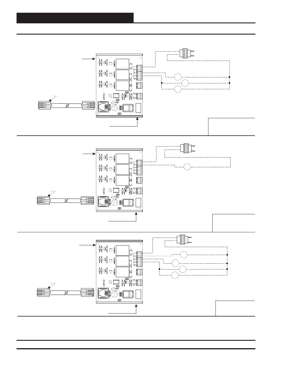
Figure 8: Expansion Board Wiring For Electric Heat Applications
WattMaster Part #OE322
Relay Expansion Board
w/ Modular Cable
Supplied by WattMaster
Mounted by Others
24VAC
COM
24 VAC Transformer Supplied
& Wired by Others. Size For
Required Contactor(s) Load.
WattMaster Part #OE322
Relay Expansion Board
w/ Modular Cable
Supplied by WattMaster
Mounted by Others
WattMaster Part # BK000047
Snaptrack Supplied by WattMaster
Mounted by Others. Remove Control
Board from Snaptrack & Mount Snaptrack on Box
WattMaster Part # BK000047
Snaptrack Supplied by WattMaster
Mounted by Others. Remove Control
Board from Snaptrack & Mount Snaptrack on Box
WattMaster Part # BK000047
Snaptrack Supplied by WattMaster
Mounted by Others. Remove Control
Board from Snaptrack & Mount Snaptrack on Box
Connect To VAV/Zone Controller
Using Modular Cable Supplied
By WattMaster
Connect To VAV/Zone Controller
Using Modular Cable Supplied
By WattMaster
Connect To VAV/Zone Controller
Using Modular Cable Supplied
By WattMaster
24VAC
COM
Fan Relay
R1
WattMaster Part #OE322
Relay Expansion Board
w/ Modular Cable
Supplied by WattMaster
Mounted & Wired by Others
24VAC
COM
C1
C1
Fan Relay
R1
1st Stage Heat Contactor
1st Stage Heat Contactor
2nd Stage Heat Contactor
2nd Stage Heat Contactor
3rd Stage Heat Contactor
3rd Stage Heat Contactor
C2
C2
C3
C3
Typical Wiring for
Single Duct Terminal
with Electric Heat
Typical Wiring for
Fan Terminal Unit
with Cooling Only
Typical Wiring for
Fan Terminal Unit
with Electric Heat
Note: 3 Stage Heating is Attained by Sizing All 3
Heating Elements For Equal KW Output. Each
Element Should be Sized for 1/3 of the Total KW
Output Required. To Achieve 3 Stage Heating the
System would be Configured to Energize
Contactor C1 for First Stage Heat. For 2nd Stage
Heat the System Would be Configured to De-
energize Contactor C1 and Energize Contactor C2
& C3. For 3rd Stage Heat the System Would be
Configured to Leave Contactor C2 & C3 Energized
and also Energize Contactor C1.
Note: 3 Stage Heating is Attained by Sizing All 3 Heating
Elements For Equal KW Output. Each Element Should be
Sized for 1/3 of the Total KW Output Required. To Achieve 3
Stage Heating the System would be Configured to Energize
Contactor C1 for First Stage Heat. For 2nd Stage Heat the
System Would be Configured to De-energize Contactor C1
and Energize Contactor C2 & C3. For 3rd Stage Heat the
System Would be Configured to Leave Contactor C2 & C3
Energized and also Energize Contactor C1.
24 VAC Contactor(s)
Supplied & Installed
By Others. 2 Amp
Max. Load Each.
24 VAC Fan
Relay &
Contactor(s)
Supplied &
Installed By
Others. 2
Amp Max.
Load Each.
Q3
R6
R3
R10
Q2
R9
R5
R2
Q1
R8
R4
R1
R7
D1
PJ1
C2
C4
VR2
C6
C1
U1
RLY
3
D2
2
RLY
D3
1
RLY
D4
K1
2RAOUT BD.
YS101714
REV. 3
V4
V3
K2
K3
V1
C5
R12
R11
R13
VR1
R14
TB1 GND
OUT
V5
+
ANALOG
+V
GND
TB3
3
COM
1
2
TB2
LM358
C3
V2
7824CT
M
I
O
SERIAL
#
Q4
Q3
R6
R3
R10
Q2
R9
R5
R2
Q1
R8
R4
R1
R7
D1
PJ1
C2
C4
VR2
C6
C1
U1
RLY
3
D2
2
RLY
D3
1
RLY
D4
K1
2RAOUT BD.
YS101714
REV. 3
V4
V3
K2
K3
V1
C5
R12
R11
R13
VR1
R14
TB1 GND
OUT
V5
+
ANALOG
+V
GND
TB3
3
COM
1
2
TB2
LM358
C3
V2
7824CT
M
I
O
SERIAL
#
Q4
Q3
R6
R3
R10
Q2
R9
R5
R2
Q1
R8
R4
R1
R7
D1
PJ1
C2
C4
VR2
C6
C1
U1
RLY
3
D2
2
RLY
D3
1
RLY
D4
K1
2RAOUT BD.
YS101714
REV. 3
V4
V3
K2
K3
V1
C5
R12
R11
R13
VR1
R14
TB1 GND
OUT
V5
+
ANALOG
+V
GND
TB3
3
COM
1
2
TB2
LM358
C3
V2
7824CT
M
I
O
SERIAL
#
Q4
24 VAC Transformer Supplied
& Wired by Others. Size For
Required Fan Relay Load.
24 VAC Transformer Supplied &
Wired by Others. Size For Required
Fan Relay & Contactor(s) Load.
24 VAC Fan Relay
Supplied & Installed
By Others. 2 Amp
Max. Load.
Expansion Board Installation & Wiring