13b. wcc iii - mcd installation guide, Input/output connections – WattMaster WM-WCC3-TGD-01B User Manual
Page 624
WCC III Technical Guide
13B-12
13B. WCC III - MCD INSTALLATION GUIDE
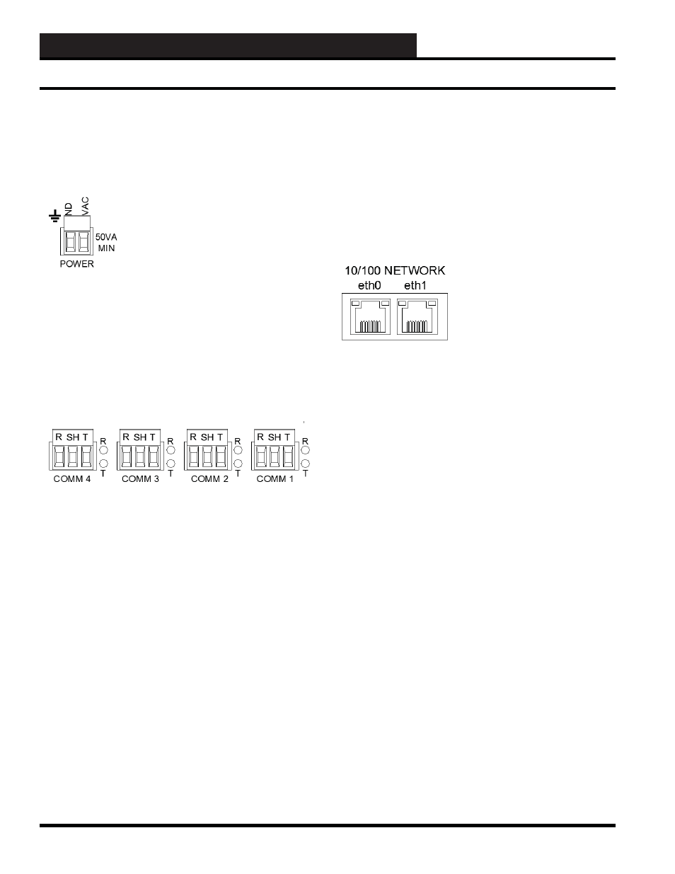
R & T COMMUNICATIONS LEDs
There are simplistic communication diagnostic LEDs that are
provided next to each one of the RS-485 connectors. The LED
marked “R” stands for “Receive”, and this red LED will fl icker
when data is received from a specifi c satellite controller. The LED
marked “T” stands for “Transmit” and this red LED will LED will
fl icker when data is transmitted by the WCCIII-MCD2 to a specifi c
satellite controller).
10/100 Network ports eth0, and eth1
The main Ethernet port on the WCCIII-MCD2 is named and
labeled “eth0”. This is the primary I/P connection to the WCCIII-
MCD2 device. See page XX for detailed instructions on how to
properly confi gure this network port for proper network access.
The auxiliary (second) Ethernet port on the WCCIII-MCD2 is
named and labeled “eth1”. This port confi guration should never
be changed or reconfi gured by the contractor or end user. It is
meant for direct connection (with a network cross-over cable) to
a Laptop that is to be used for setup, confi guration, updating, and
troubleshooting, or to a dedicated WCC3 computer that would be
set up to run the various WCC3 type programs that connect to the
WCCIII-MCD2 via a network connection.
Each port—etho0 and eth1—has two built in LEDs.
The Left LED is a bi-color Network Speed indicator:
LED Yellow on – Operating as a Gigabit connection (1000 Mbps)
LED Green on – Operating as a 100-Mbps connection.
LED Off – Operating as a 10-Mbps connection.
The Right LED is Link/Activity indicator:
LED Blinking – There is activity on this port.
LED Off – There is no network link established.
Input/Output Connections
Various I/O connections that are on the
Bottom Side of the WCCIII-MCD2 Device
24VAC Power Connector
A two position de-pluggable connection is provided for power
connection to the WCCIII-MCD2 device. The WCCIII-MCD2 is
powered off of dedicated 120VAC to 24VAC@50VA transformer
that WattMaster Controls supplies with each WCCIII-MCD2
device. The 24VAC power de-pluggable connector is considered
to be “polarized” with a 24VAC side and a GND side. Correct
power polarity must be observed.
RS-485 Connectors
The WCCIII-MCD2 device provides four separate RS-485
connections. Each one of these three position de-pluggable
RS-485 connections are distance rated for up to 4000 feet of
communications loop cable when using approved communications
wire. (WM Part # or WM Part #). This communications cable is
described as 18 gauge single pair twisted, with a shield, and drain
wire. The Drain wire (Shield) must be connected between the
WCCIII-MCD2 device and all of the Satellite controllers.
Wiring between the WCCIII-MCD2 and the satellite
controllers:
Basic rule of thumb when wiring communications from the
WCCIII-MCD2 to any and all Satellite connections: Wire “R”
connections to “R” connections, Wire “T” connections to “T”
connections, Wire “SH( SHLD)” connections to “SH (SHLD)”
connections, and there should not be an issue with communications
wiring.