Occupied mode sequences, Sequence of operations, Space heating mode – WattMaster WM-WCC3-TGD-01B User Manual
Page 828: Table 4: fan & reheat relay staging
Space Heating Mode
Occupied Space Heating mode is initiated by the temperature in the
space falling below the Occupied Heating Setpoint.
If the HVAC unit is in the Supply Air Cooling mode and another VAV/
Zone Controller has a heating demand, the damper/airfl ow for the VAV/
Zone Controller requiring heating will position itself to provide the
Cooling Minimum amount of air into the space. No modulation open
will occur because the space does not want the cold air currently being
supplied by the air handler.
When the HVAC unit is in the Occupied Supply Air Heating mode, the
damper will be held at the Heating Minimum position until the space
temperature falls to within 0.5 ºF of the Occupied Heating Setpoint.
As the space temperature falls below the heating setpoint, the damper/
airfl ow calculation causes the air valve to open proportionally until the
maximum setpoint is achieved at 1.5 ºF below the setpoint. This is a 2
ºF proportional window starting 0.5 ºF above the heating setpoint to 1.5
ºF below the heating setpoint.
Two different confi gurations are available for the Occupied Space
Heating mode. If the box is confi gured to allow reheat during HVAC
heat mode, the reheat relays can be activated even when the VAV/Zone
Controller is in the Supply Air Heating mode. If the box is confi gured
not to allow reheat when the HVAC unit is in Heat mode, the box heat
relays will be de-energized when the VAV/Zone Controller is in Supply
Air Heating mode. In either confi guration, when the VAV/Zone Control-
ler is in the Supply Air Heating mode, the damper will modulate open
proportionally to the space demand. The proportional window for the
space temperature is 0.5 ºF above to 1.5 ºF below the heating setpoint.
This allows the space to take advantage of the warm supply air in the
duct.
The VAV/Zone Controller can activate auxiliary heating relays if the
Expansion Module has been connected and the correct number of heat-
ing stages (1, 2 or 3) has been confi gured. During demands for heat, the
fi rst stage will activate whenever the space temperature drops below the
heating setpoint. The second stage will activate if the space temperature
falls 1.0 ºF below the heating setpoint. The third stage will activate if
the space temperature falls 2.0 ºF below the heating setpoint. There is a
two-minute delay between staging. This prevents stages from activating
at the same time. Once a heating stage has been activated, it must remain
on for at least one minute. Once it has been deactivated, it must remain
off for at least two minutes. The third stage relay will deactivate when
the space temperature rises to within 1.0 ºF of the heating setpoint. The
second stage relay will deactivate when the space temperature rises to
the heating setpoint. The fi rst stage relay will deactivate when the space
temperature rises above the heating setpoint by 1.0 ºF. See Table 4 for a
complete layout of the various fan & heat relay staging points.
Modulating (Proportional) Heat
The VAV/Zone Controller Actuator Package expansion module also
provides an analog output for control of a modulating hot water valve
or SCR electric heater. It provides a 0-10 VDC signal to control the
heating device. When the space temperature drops to 0.5 ºF above the
Heating Setpoint the output starts at 0 VDC and ramps up to 10 VDC
at 1.5 ºF below the Heating Setpoint.
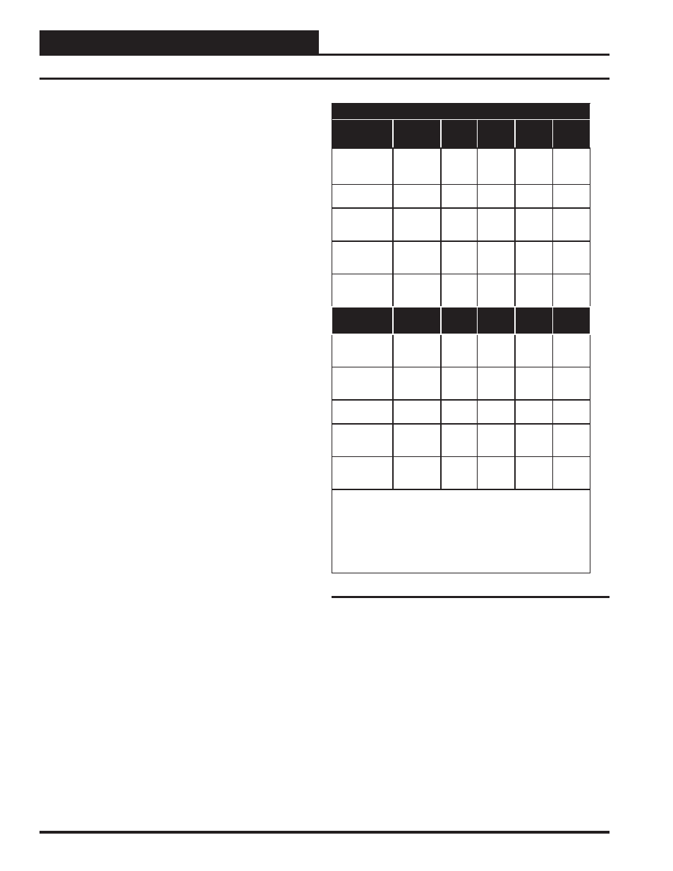
Fan & Reheat Relay Staging
Relays Stage
On At
Series
Fan
Parallel
Fan
Heat
Stage 1
Heat
Stage 2
Heat
Stage 3
0.5 ºF Above
Box Heat
Setpoint
See
Note 1
See
Note 2
At Box Heat
Setpoint
See
Note 1
X
1.0 ºF Below
Box Heat
Setpoint
X
2.0 ºF Below
Box Heat
Setpoint
X
0.5 ºF Below
Box Heat
Setpoint
Relays Stage
Off At
Series
Fan
Parallel
Fan
Heat
Stage 1
Heat
Stage
2
Heat
Stage 3
1.0 ºF Above
Box Heat
Setpoint
See
Note 1
See
Note 2
1.0 ºF Above
Box Heat
Setpoint
See
Note 1
X
At Box Heat
Setpoint
X
1.0 ºF Below
Box Heat
Setpoint
X
0.5 ºF Above
Aux. Heat
Setpoint
Notes: 1) The Series Fan will run continuously any time the
VAV/Zone Controller is in Occupied Mode.
2) On parallel fan powered terminal units, the fan will run when-
ever Space Heating mode is active. At all other times, the fan
will only activate if the damper/airfl ow is below a user defi ned
low limit setting.
Table 4: Fan & Reheat Relay Staging
Series Flow Fan Terminals
If the VAV/Zone Controller has been confi gured as a Series Fan Powered
terminal unit, the series fan relay will activate and run the series box fan
continuously anytime the VAV/Zone Controller is in occupied mode.
In all cases, before the series box fan can be activated, the air damper
is driven fully closed and held that way for 30 seconds to make sure
the series box fan hasn’t inadvertently started to spin backwards. Once
the series box fan starts, it waits an additional 10 seconds to allow the
fan to spin up before it starts to open the damper and introduce airfl ow
from the HVAC unit fan.
Occupied Mode Sequences
24
VAV/Zone Controller Actuator Package Technical Guide
Sequence of Operations