Rs-485 communications, Tuc-2r troubleshooting with a digital voltmeter – WattMaster WM-WCC3-TGD-01B User Manual
Page 466
10. RS-485 COMMUNICATIONS
WCC III Technical Guide
10-14
TUC-2R Troubleshooting with a Digital Voltmeter
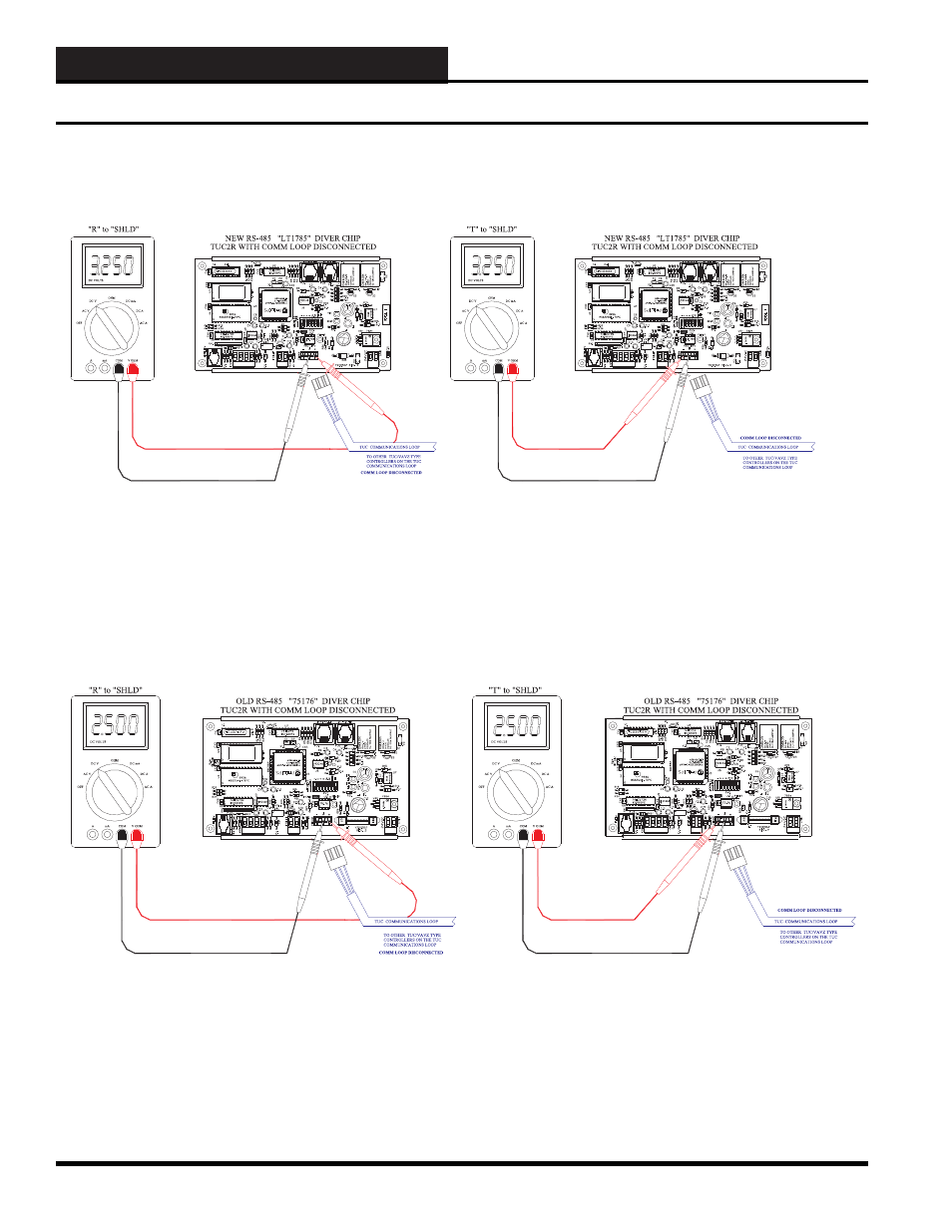
Figure 10-17: Typical TUC-2R RS-485 TUC Communications DC Voltage Measurements with the TUC COMM
Loop Disconnected – LT1785 Driver
Figure 10-18: Typical TUC-2R RS-485 TUC Communications DC Voltage Measurements with the TUC COMM
Loop Disconnected – 75176 Driver
TUC-2R Communications Troubleshooting with a Digital Voltmeter
The voltage measurements in Figure 10-17 are approximate voltages. Newer TUC-2R Controllers use a different RS-485 driver chip.
These voltage measurements are taken when the power to the TUC-2R Controller is “ON” and the RS-485 TUC communications loop is
disconnected. These two voltages will not fl uctuate. The voltage measurement from “T” to “SHIELD” should be around 3.25 VDC. The
voltage measurement from “R” to “SHIELD” should be around 3.25 VDC. Typical bad voltage measurement values would be anything
above 3.8 VDC and anything below 1.5 VDC.
The voltage measurements in Figure 10-18 are approximate voltages. Older TUC-2R Controllers used a different RS-485 driver chip.
These voltage measurements are taken when the power to the TUC-2R Controller is “ON” and the RS-485 TUC communications loop is
disconnected. These two voltages will not fl uctuate. The voltage measurement from “T” to “SHIELD” should be around 2.50 VDC. The
voltage measurement from “R” to “SHIELD” should be around 2.50 VDC. Typical bad voltage measurement values would be anything
above 3.8 VDC and anything below 1.5 VDC.