General instructions, Data registers – WattMaster WM-WCC3-TGD-01B User Manual
Page 63
1. GENERAL INSTRUCTIONS
WCC III Technical Guide
1-9
Time & TimeB
These logical addresses are the actual time on HH:MM (TIME) and
minutes-since-midnight (TIMEB) formats. They are considered
analog values and have value ranges of 0000 to 2359 (TIME), and
0000 to 1439 (TIMEB).
Typical application of these logical addresses includes use in
the Dual Limit mode, allowing such modes of control as “On-
Between-Times” and “Off-Between-Times.”
NEWSEC, NEWMIN, NEWHR, NEWDAY, & NEWMON
These logical addresses are considered binary values and are based
on real-time. They have a pulse-type nature in that each of these
addresses has a value of one (or ON) for one second after the
occurrence of the specifi ed event. After the one second ON period
has elapsed, the value returns to zero (or OFF).
These addresses have several uses throughout the system. One
example would be the generation of a variable duty cycle output.
When used in conjunction with the separate “Minimum ON/OFF”
timers, these addresses can achieve cycles of from one second to
several days with a wide range of cycles.
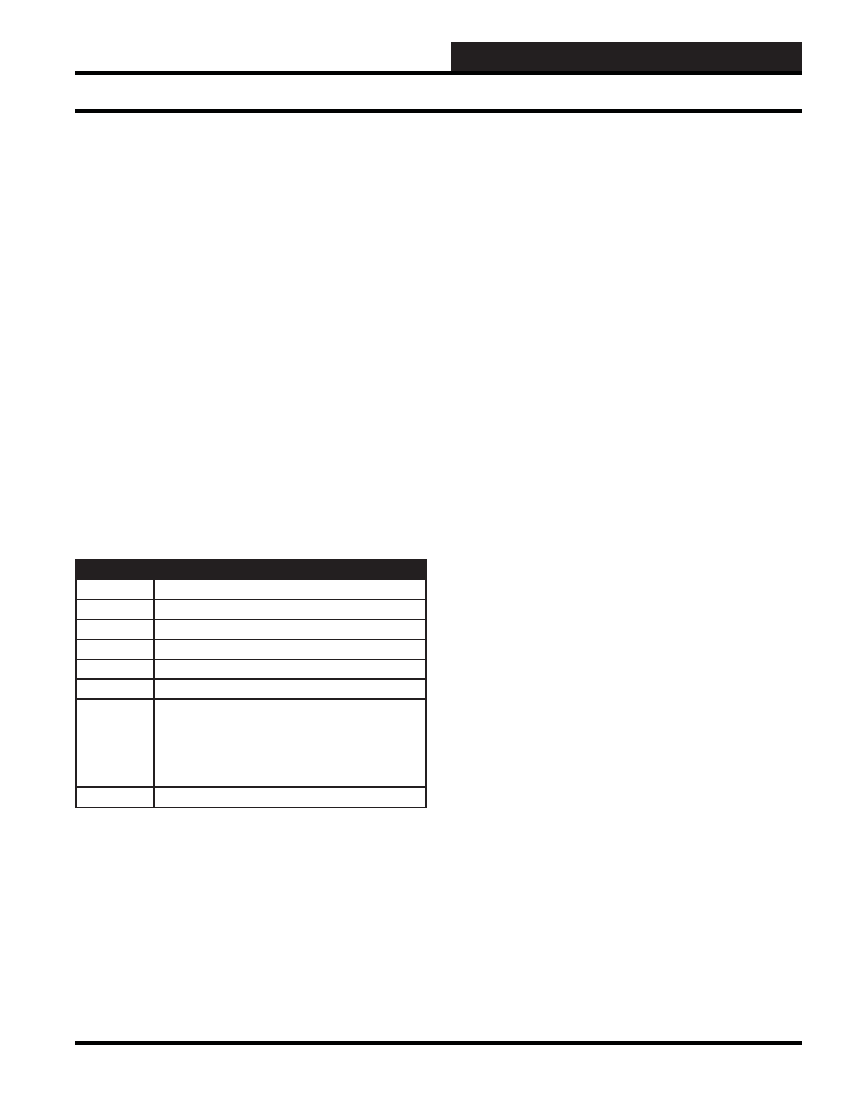
Examples of “point addresses” within the system:
Name
Description
GA12
Global Analog #12
135A5
Satellite #135, Analog Input #5
A5
Analog Input #5, Current Satellite
W12
Week Schedule #12
S27
Optimal Start #27
C1
Setpoint Comparator on Analog Input #1
K1h
When K1h is ON, the relay within the satellite
controller which connects the electrical path
between the “H” and “COM” terminals on
channel 1 of the satellite controller is closed.
When K1h is OFF, the circuit is open.
14P3
Satellite #14, Analog Output #3.
Data Registers
The WCC III system has some capabilities built into the software
that are very helpful, and you should be aware of them. There is
a Data Register associated with each of the H/C Control Output
Screens. A H/C Control Output Screen allows the user to tell
the satellite controller when to open and close the binary output
contacts. A H/C Control Output Screen can be a Time Clock, EA
Driver, or Dual Limit Mode Screen.
Time Clock
When the H/C Control contact on the satellite controller is
controlled by a Time Clock Screen, the contact opens and closes
based on time only. For example, a Time Clock Screen can be used
to run a water circulating pump from 8:00 am to 5:00 pm, Monday
through Friday. Each Time Clock Screen has a Data Register
associated with it.
The Data Register is an analog value which is the time in seconds
since the satellite controller binary output contact closed. Assume
the water circulating pump is controlled by satellite controller
contact K1h. That is to say, the “COM” to “H” contact on channel
1 of the satellite controller closes to complete a 24 VAC signal to
run the pump.
The Data Register for a Time Clock Screen is named RnA or RnB.
R stands for data register, n refers to channel 1-8 of the satellite
controller, A means the “COM” to “H” contact, and B means the
“COM” to “C” contact. Therefore, the Data Register for contact
K1h is R1A. As contact K1h closes, the Data Register for contact
Klh (R1A) starts recording time in seconds. That is to say, the value
of R1A is the time in seconds since contact K1h closed.
RnA = Time in seconds since COM to H contact closed
(9999 sec max)
RnB = Time in seconds since COM to C contact closed
(9999 sec max)
The Data Register for a Time Clock Screen might be used to
start one piece of equipment after another has been started. For
example, assume we want to start an air handler two minutes after
the water circulating pump starts. The pump would be controlled
by a Time Clock Screen as mentioned above. The air handler would
be controlled using a Dual Limit Screen. The analog input value
for the Dual Limit Screen would be R1A, which is time in seconds
since the pump started. The Dual Limit Screen is set up to close the
contact for the air handler when the value of R1A is between 120
seconds and infi nity.
The data register will also record time in negative seconds. When
the contact opens, the data register value will begin counting -1,
-2, etc.
Data Registers