WattMaster WM-WCC3-TGD-01B User Manual
Page 523
12. WCC III INSTALLATION
GUIDE
WCC III Technical Guide
12-27
Sequence of Operation
When the SAT III controller makes COM to H, 24 VAC is supplied
to the “HEAT” terminal on the PI board which causes the DC output
voltage supplied by the PI board to increase the output voltage at
the preset rate.
When the SAT III controller makes COM to C, 24 VAC is supplied
to the “COOL” terminal on the PI board which causes the DC
output voltage supplied by the PI board to decrease the output
voltage at the preset rate. When both the COM to H and COM to C
terminals are open on the SAT III controller, the DC output voltage
supplied by the PI board will remain at its present value.
Previous “Old” SAT II Type Binary
Input with Time Delay Board
The SAT II type Binary Input with Time Delay board is an optional
integrated circuit board which can interface with the “old” SAT II
as well as the “new” SAT III controllers to allow it to monitor the
status of remote mounted binary (on/off) devices such as switch
closures, air fl ow switches, etc. One binary input board enables the
SAT II or SAT III controller to monitor up to 8 binary inputs, and 2
binary input boards can be used with 1 SAT II or SAT III controller
for a total of 16 binary inputs per SAT II or SAT III controller.
The SAT III controller comes standard with two eight-position
dipswitch switches on its front panel labeled L1 - L8 and L9 - L16
which are in effect manually controlled binary inputs. The SAT
III controller monitors the on/off status of these switches and can
control and/or alarm based on the position of these dipswitches.
The Binary Input with Time Delay board allows the eight-position
dipswitches to be replaced with a terminal connection points which
will accept wiring for remote-mounted binary input devices.
The SAT III controller has two sets of eight-position dipswitches
on its front panel labeled L1 - L8 and L9 - L16. Switches L1-L8 are
housed together in one dipswitch, and switches L9-L16 are housed
together in another dipswitch. One of the dipswitches is removed
for each Binary Input with Time Delay board, and is then replaced
with a ribbon cable that connects the Binary Input with Time Delay
board to the SAT III controller. The binary devices to be monitored
are then wired to the terminal strip of the Binary Input with Time
Delay board. The Binary Input with Time Delay board requires a
24 VAC power source. Warning: You must observe polarity on the
24 VAC and GND connections of both the Binary Input with Time
Delay board and the SAT III controller, as the grounds must be the
same. See Section 3 for further details on Satellite programming
instructions.
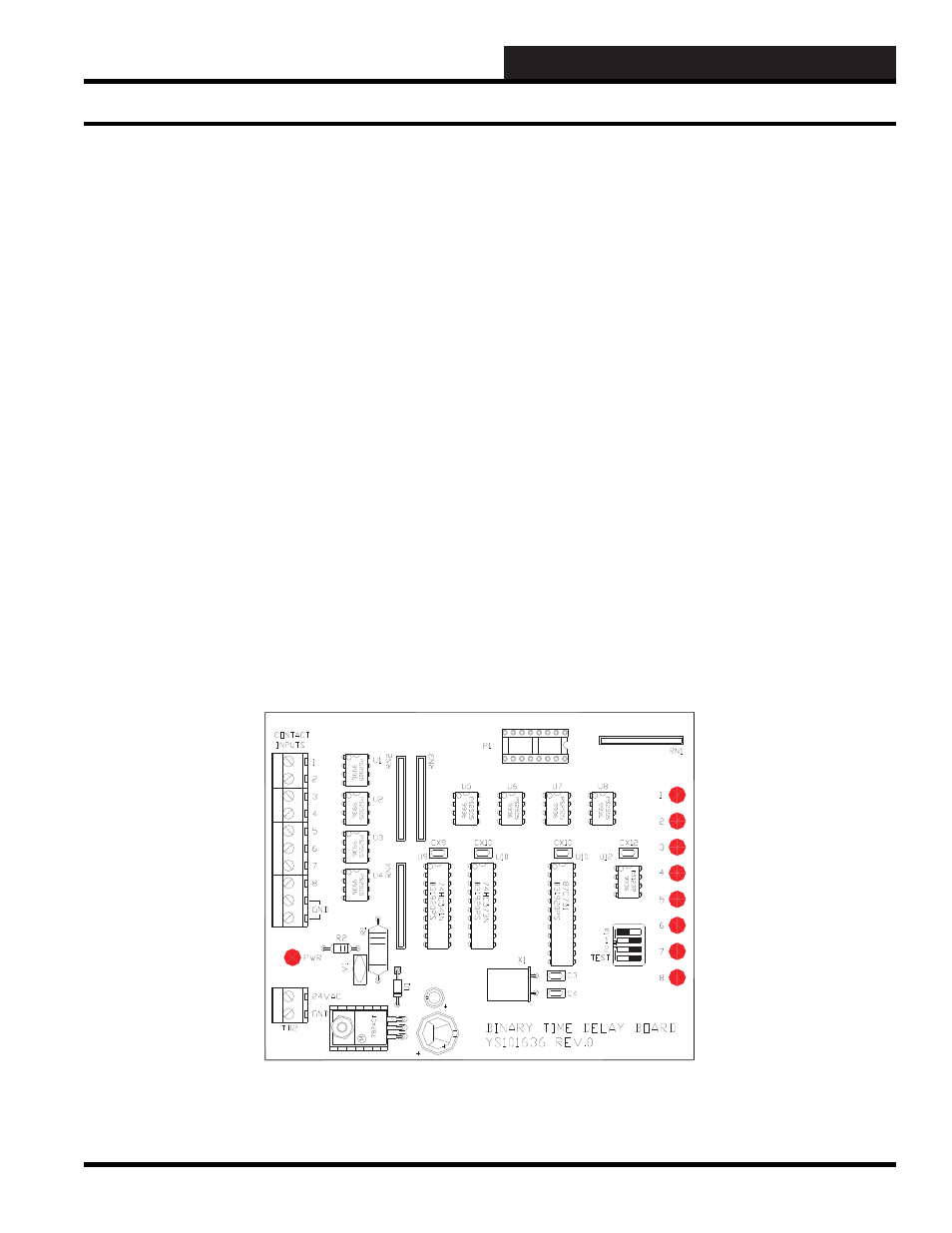
Figure 12-23: The “old” SAT II type Binary Input with Time Delay board
Old SAT II Type Binary Input with Time Delay Board