Rs-485 communications – WattMaster WM-WCC3-TGD-01B User Manual
Page 455
10. RS-485 COMMUNICATIONS
WCC III Technical Guide
10-3
RS-485 Wire Considerations
The RS-485 wire specifi cations are generally a stranded 18-
gauge, 2-wire twisted pair with shield. 18-gauge stranded wire is
mandatory to ensure a good connection with the ¼-inch Sta-Con
connectors which are used to terminate the wires at the WCC III -
MCD and at the satellite controllers.
The old SAT II Manchester communications loop was supposed to
have used a 2-wire twisted pair with shield, but this was not used
in every installation. This old SAT II communications loop should
not be used for the new SAT III communications loop. A new RS-
485 communications loop should be run to each new replacement
SAT III Controller. The shield wire must be used on the new SAT
III Controller as it provides a “ground” reference for the RS-485
communication loop.
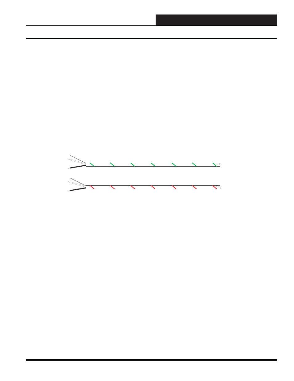
<<<LOCAL LOOP>>> AZWR-LL-WG-18>>> E76191 CL2P 18AWG (UL) 012112 FT
<<<NETWORK LOOP>>> AZWR-NL-WR-18>>> E76191 CL2P 18AWG (UL) 012112 FT
WATTMASTER LOCAL LOOP WIRE
WATTMASTER NETWORK LOOP WIRE
Figure 10-3: WattMaster Controls various communications loop wire
RS-485 Wire & Power and Switchable RS-485 Communications Board
Power and Switchable RS-485
Communications Board
“Wire Nuts” on the RS-485 communications loop should be avoided
at all costs. As an alternative to the “Wire Nuts”, WattMaster
Controls has a Power and Switchable RS-485 Communications
Board - WattMaster part #PL102224. The Power and Switchable
RS-485 Communications Board can be thought of as a 24-VAC
power and communication distribution system for the SAT III
communications loop that will aid in initial startup and future
troubleshooting of the SAT III communications loop. The Power
and Switch Boards should be used on a fl oor-by-fl oor basis. The
board is sold alone or in a small metal electrical enclosure. See
Figure 10-4.
This circuit board was designed to be used as a central connection
point for the SAT III communications loop. The eight switches are
provided only to disconnect the RS-485 communications loop for
troubleshooting purposes.
Wiring for the communication connections are as follows: “R”
to “R,” “T” to “T,” and “SHLD” to “SHLD” or “SH.” Connect
the wiring from the SAT III to a SAT III, SAT 3C/D/F, or SAT 3P
Controller. These eight push-button switches only disconnect the
communications loop. THEY DO NOT SWITCH POWER ON/
OFF.
This circuit board may be also used as a separate central connection
point for the SAT 3C/D/F - TUC communications loop.
Wiring for the communications connections are as follows: “R” to
“R,” “T” to “T,” and “SHLD” to “SHLD” or “SH.” Connect the
wiring from TUC controller to TUC controller. But on the SAT
3C/D/F controller, the TUC “R” connection must be wired to the
SAT 3C/D/F “T” connection, and the SAT 3C/D/F controller “R”
connection must be wired to the TUC “T” connection.
WattMaster Controls sells two versions of 18-gauge, 2-wire twisted
pair with shield communications wire:
•
WattMaster part #WR-NL-WR-18 - marked “Network
Loop” with a red stripe for rapid identifi cation. This
wire should be run from the WCC III - MCD to the
SAT III, SAT 3C/D/F, SAT 3P, and then to the next
SAT 3-type controllers.
•
WattMaster part #WR-LL-WG-18 - marked “Local
Loop” with a green stripe for rapid identifi cation for the
TUC loops that run from the SAT 3C/D/F controllers to
the TUC controllers.