Wcc3.exe screen descriptions, Logic switch screen, Wcc iii technical guide 3-78 – WattMaster WM-WCC3-TGD-01B User Manual
Page 192: Confi g on board off board, Time delay, Sat iii
WCC3.EXE SCREEN DESCRIPTIONS
WCC III Technical Guide
3-78
Confi g
ON Board
OFF Board
ON Board is the corresponding dipswitch on the cover of the
SAT III, including the older binary input board that plugs into the
dipswitch socket. OFF Board is the new HSS port and the new
HSS binary input board.
8
7
SAT ADDRESS
2
1
4
8
A 3 WIRE ROOM SENSOR WILL NOT
REQUIRE A LOAD RESISTOR WHEN SET
FOR A 1 VOLT INPUT.
WattMaster Controls Inc.
BINARY
INPUTS
BINARY
INPUTS
L8
ON OFF
128
32
16
64
L4
L3
L2
L1
L6
L5
L7
L11
L12
ON OFF
L10
L9
ON OFF
L15
L16
L14
L13
C
H
4
3
5
6
2
1
LOCAL SET
STATUS 2
STATUS 3
STATUS 1
HSS XMIT
LOCAL SET
LOCAL SET DISABLE
BATT ON/ OFF
PULSE INPUT
OPTION 1
TEST
OPTION 3
OPTION 2
ON OFF
STATUS
HSS REC
SAT XMIT
SAT REC
ANALOG INPUT
JUMPER SELECTION
A 2 WIRE ROOM SENSOR WILL REQUIRE
A 300 OHM LOAD RESISTOR WHEN SET
FOR A 1 VOLT INPUT.
A 4 TO 20 mA SENSOR WILL REQUIRE A
50 OHM LOAD RESISTOR WHEN SET FOR
A 1 VOLT INPUT, OR A 250 OHM LOAD
RESISTOR WHEN SET FOR A 5 VOLT INPUT.
CURRENT
INPUT
THERMISTOR
INPUT
0 - 1V
0 - 5V
0 - 10V
THERM
0 - 1V
0 - 5V
0 - 10V
THERM
0 TO 10V
INPUT
0 TO 5V
INPUT
0 TO 1V
INPUT
0 - 10V
0 - 1V
0 - 5V
0 - 10V
THERM
0 - 1V
0 - 5V
THERM
0 - 1V
0 - 5V
0 - 10V
THERM
PROGRAMMABLE CONTROLLER
SAT III
A
25
0VAC
~
5A
30
VD
C
SA
VD
E
G5
Q-
1A
4
OM
R
O
N
24
V
24VAC
120VAC
TO OTHER
SAT III OR TO
WCC III - MCD
WIRE "T" TO "T"
"R" TO "R"
"SHD" TO "SHD"
TO OTHER
SAT III OR TO
WCC III - MCD
WHEN CONNECTING POWER
OBSERVE POLARITY
CONNECTION FROM SAT III TO BINARY INPUT BOARD
USING THE "OLD" RIBBON CABLE CONNECTION METHOD
DRY INPUT CONTACTS ONLY
24VA
C
GND
TWO BINARY INPUT BOARDS MAY BE WIRED TO
THE SAT III CONTROLLER USING THIS METHOD.
CONNECT THE FIRST ONE TO L1 TO L8 SWITCH
BINARY INPUTS, AND THE SECOND ONE TO L9 TO
L16 SWITCH BINARY INPUTS.
SEE MANUAL FOR DIP
SWITCH SETTINGS
REPLACE THE DIP SWITCH IN
THE SAT III COVER WITH THE
SUPPLIED RIBBON CABLE.
OBSERVE POLARITY
PIN #1
PIN #1
STRIPE
IS
PIN
#1
CONTACT CLOSURE TO GND
ONLY
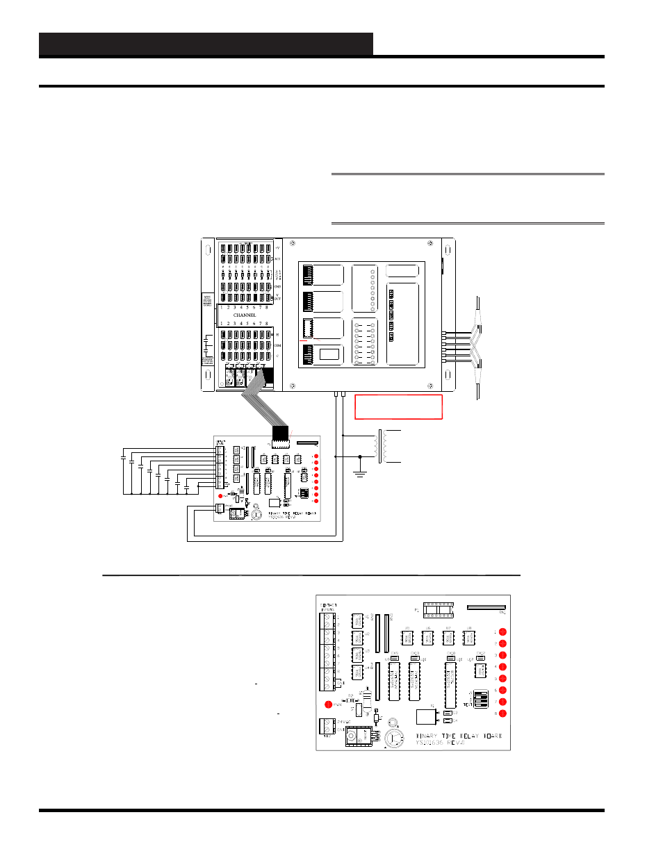
OLD SAT II STYLE BINARY INPUT WITH TIME DELAY BOARD (YS101636)
The Binary Input with Time Delay board provides a terminal point for
landing wire for a external input switch / relay contact. It interfaces to the
SAT III controller via a supplied 16 pin ribbon cable with "DIP" connectors
on both sides.
Connect "P1" on the Binary Input board to one of the two removable
DIPSWITCHES on the cover of the SAT III controller. These two switches
are labeled Binary Inputs on the cover of the SAT III controller.
The eight Binary Inputs are dry contact closures to ground only.
There is a time delay switch on the Binary Input with time delay board.
This time delay switch determines how long the input will stay on after a
momentary switch contact is applied to the input of the Binary Input Board.
With the time delay dipswich (1 to 4) all OFF, there is no delay ON for all
eight inputs. Time Delay dipswitch (1 - .5) ON there is a
1
2
hour delay ON
for all eight inputs. Time Delay dipswitch (2 - 1) ON there is a 1 hour
delay ON for all eight inputs. Time Delay dipswitch (3 - 2) ON there is a
2 hour delay ON for all eight inputs. These Dipswitch settings are additive.
With Time Delay dipswitch (1 - .5, 2 - 1, and 3 - 2) ON there is a 3
1
2
hour
delay ON for all eight inputs.
This Binary Input board power requirements are 24VAC and it draws 5 VA.
The 24VAC power Connection is T 2, and you must observe polarity when
B
connecting this power connection to the SAT III.
WARNING:
OBSERVE POLARITY
BETWEEN THE SAT III AND THE
BINARY INPUT BOARD - GROUND
CONNECTIONS MUST BE THE SAME.
120VAC WIRING IS BY OTHERS
THE VA RATING FOR THE SAT III CONTROLLER IS 15VA.
THE VA RATING FOR THE WCC3 BINARY INPUT BOARD (OE431-01) IS 5 VA.
THE VA RATING FOR THE WCC3 V-OUT RELAY BOARD (OE430-01) IS 10 VA.
THE VA RATING FOR THE WCC3 V-OUT RELAY BOARD (OE430-02) IS 20 VA.
Time Delay
The Time Delay value will be displayed in this location. When
the input closes, it will stay on for this amount of time. Time is in
minutes.
NOTE:
This function is only used with the HSS Binary Input
Board.
Logic Switch Screen