Rs-485 communications – WattMaster WM-WCC3-TGD-01B User Manual
Page 463
10. RS-485 COMMUNICATIONS
WCC III Technical Guide
10-11
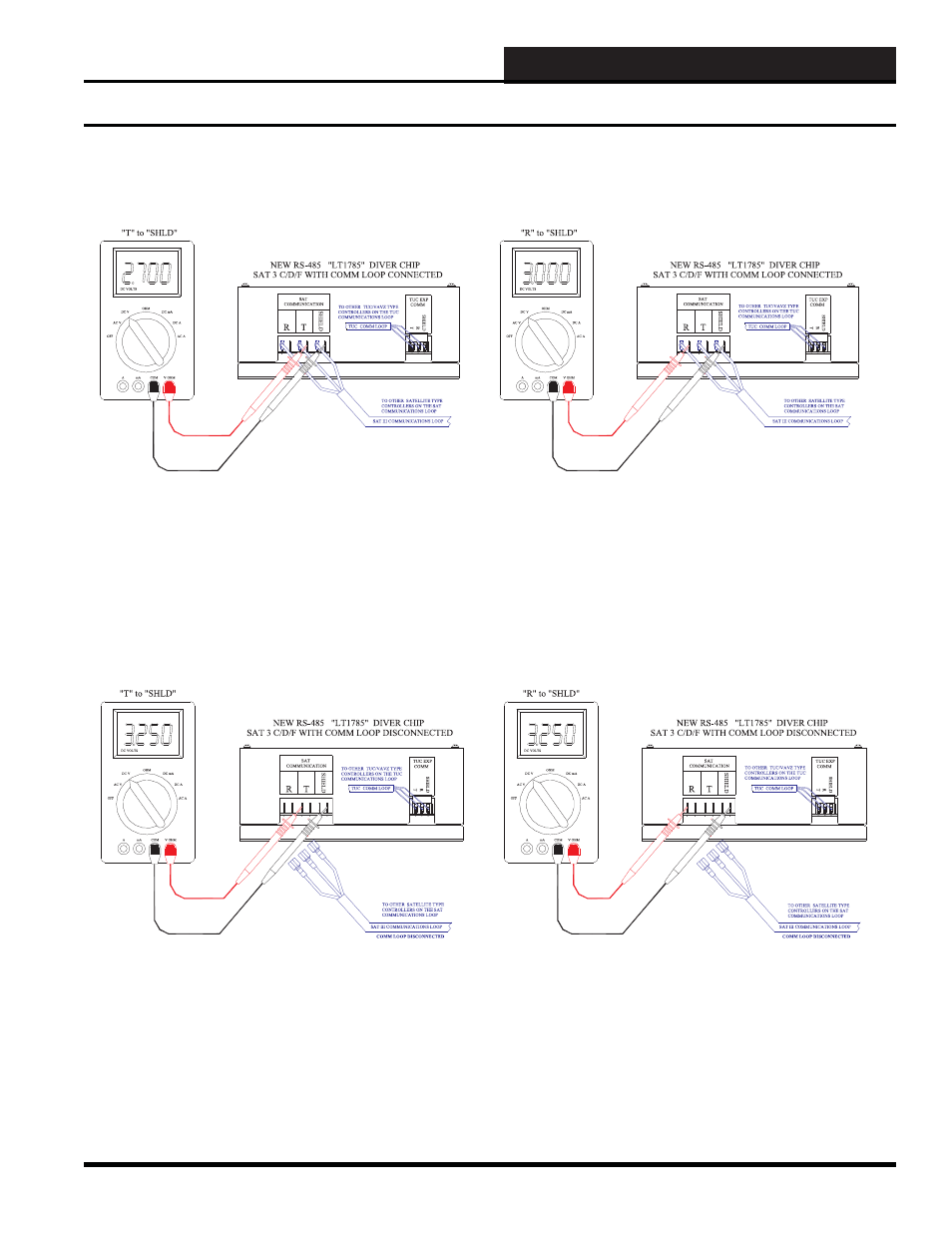
The voltage measurements in Figure 10-11 are approximate voltages. These voltage measurements are taken when the power to the SAT
3C/D/F Controller is “ON” and the RS-485 SAT communications loop is connected. These two voltages will fl uctuate slightly and also will
momentarily “fl ip” to the other meter reading’s value. The voltage measurement from “T” to “SHIELD” should be around 2.7 VDC. The
voltage measurement from “R” to “SHIELD” should be around 3.00 VDC. Typical bad voltage measurement values would be anything
above 3.8 VDC and anything below 1.5 VDC. Helpful hint: Removal of the SAT 3C/D/F cover may aid in measuring the communication
loop voltages.
SAT 3C/D/F Troubleshooting with a Digital Voltmeter
Figure 10-11: Typical SAT 3C/D/F RS-485 Satellite Communications DC Voltage Measurements with the SAT
COMM Loop Connected
Figure 10-12: Typical SAT 3C/D/F RS-485 Satellite Communications DC Voltage Measurements with the SAT
COMM Loop Disconnected
SAT 3C/D/F Communications Troubleshooting with a Digital Voltmeter
The voltage measurements in Figure 10-12 are approximate voltages. These voltage measurements are taken when the power to the SAT
3C/D/F controller is “ON” and the RS-485 SAT communications loop is disconnected. These two voltages will not fl uctuate. The voltage
measurement from “T” to “SHIELD” should be around 3.25 VDC. The voltage measurement from “R” to “SHIELD” should be around
3.25 VDC. Typical bad voltage measurement values would be anything above 3.8 VDC and anything below 1.5 VDC. Helpful hint:
Removal of the SAT 3C/D/F cover may aid in measuring the communication loop voltages.