Controller installation & wiring, Figure 6: slaved zone wiring & connection diagram – WattMaster WM-WCC3-TGD-01B User Manual
Page 778
VAV/Zone Controller Technical Guide
Operator Interface
10
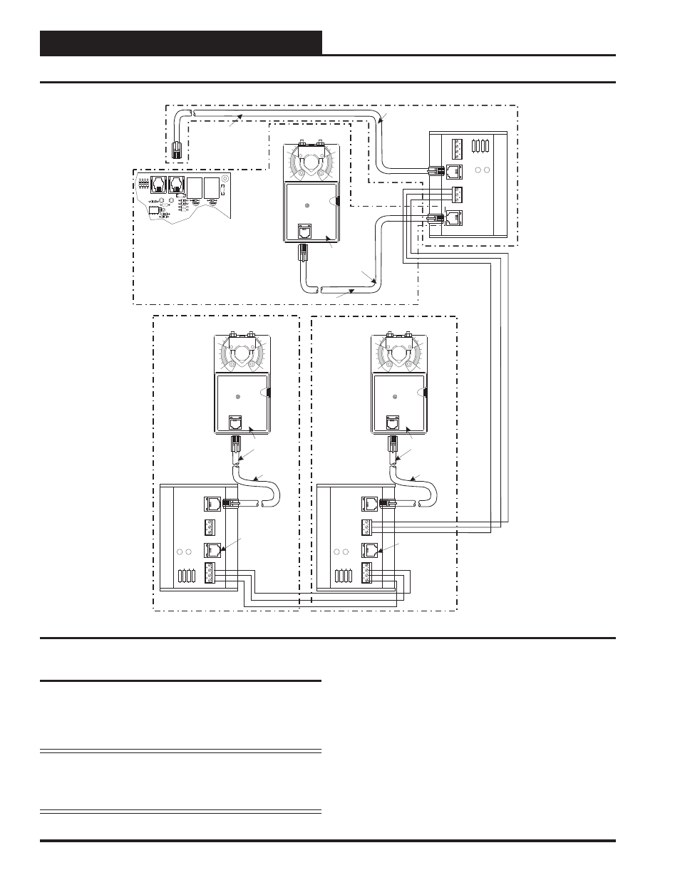
Slaved Zone Damper Wiring
For large zones it may be necessary to have more than one air damper
controlled by a VAV/Zone Controller and its associated space sensor.
The WCC III system allows for connecting up to two additional slaved
zone dampers to the master VAV/Zone Controller. Slaving is not avail-
able for pressure independent damper applications.
NOTE: Each slaved actuator is rated at 6 VA each. This 6 VA
load must be included in the transformer sizing. See
the previous section regarding transformer sizing for
complete information.
Two Slave Wiring Adapters (OE267), consisting of a slave wiring inter-
face card and modular cable, are supplied with the OE523 Round Slaved
Zone Damper, OE738 Slaved VAV/Zone Rectangular Damper Kit, and
the OE282-03 Slaved VAV/Zone Damper Kit. These are required when
attaching slave actuator(s) to the master zone damper. One slave wiring
interface card should be mounted in the control enclosure of the master
VAV/Zone Controller. It is mounted by fastening the plastic snap-track
to the control enclosure with sheet metal screws provided. The other card
is mounted in the control enclosure of the slaved zone damper. Fasten
it in the control enclosure of the slaved zone damper as was previously
done with the master VAV/Zone Controller. Run 24 AWG minimum
wire between the slave wiring interface cards. Connect modular cables
to the slave wiring interface cards and to the zone actuators as shown.
See Figure 6 for complete wiring details.
SLAVED- ZONE ACTUATOR #2
(WHEN USED)
SLAVED-ZONE ACTUATOR #1
ZONE ACTUATOR #1
(MASTER)
MODULAR CABLE
MODULAR CABLE
MODULAR
CABLE
MODULAR
CABLE
1
1
0
0
1
0
(PL101824) BYPASS AND
SLAVE INTERFACE CARD
(PL101824) BYPASS AND
SLAVE INTERFACE CARD
(PL101824) BYPASS AND
SLAVE INTERFACE CARD
HZ000095
HZ000095
HZ000095
HZ000095
OE282
OE282
OE282
(OE324) ZONE CONTROLLER BOARD
FROM
ZONE
CONTROLLER
BYP
ASS
AND
SLA
VE
INTERF
ACE
YS101824
TO
ACTUA
TO
R
OPEN
CLOSE
FDBK
OPEN
GND
GND
PJ1
PJ2
LD2
LD1
OPEN
CLOSE
CLOSE
TB1
TB2
FROM
ZONE
CONTROLLER
BYP
ASS
AND
SLA
VE
INTERF
ACE
YS101824
TO
ACTUA
TO
R
OPEN
CLOSE
FDBK
OPEN
GND
GND
PJ1
PJ2
LD2
LD1
OPEN
CLOSE
CLOSE
TB1
TB2
NOT USED FOR
THIS APPLICATION
NOT USED FOR
THIS APPLICATION
FROM
ZONE
CONTROLLER
BYP
ASS
AND
SLA
VE
INTERF
ACE
YS101824
TO
ACTUA
TO
R
OPEN
CLOSE
FDBK
OPEN
GND
GND
PJ1
PJ2
LD2
LD1
OPEN
CLOSE
CLOSE
TB1
TB2
OE520, OE736, OE742
OE267
PJ2
PJ1
ACTUATOR
EXPANSION
OE523,
OE738,
OE282-03
OE523,
OE738,
OE282-03
Figure 6: Slaved Zone Wiring & Connection Diagram
Controller Installation & Wiring