Start-up & commissioning – WattMaster WM-WCC3-TGD-01B User Manual
Page 783
Operator Interface
VAV/Zone Controller Technical Guide
15
Start-Up & Commissioning
Power Wiring
One of the most important checks to make before powering up the
system for the fi rst time, is to confi rm proper voltage and transformer
sizing for the VAV/Zone loop. Each VAV/Zone Controller requires 6 VA
of power delivered to it at 24 VAC. See pages 7, 8, & 9 of this manual
for complete wiring and transformer sizing information for the VAV/
Zone Controller.
Check all connectors to be sure they are completely pushed and locked
into their connectors. Confi rm that all sensors required for your system
are mounted in the appropriate location and that the cables are plugged
into the correct connectors on the VAV/Zone Controller. Check the actua-
tor cable and be sure it is plugged in and secured to the modular connector
on the actuator and the VAV/Zone Controller board modular connector.
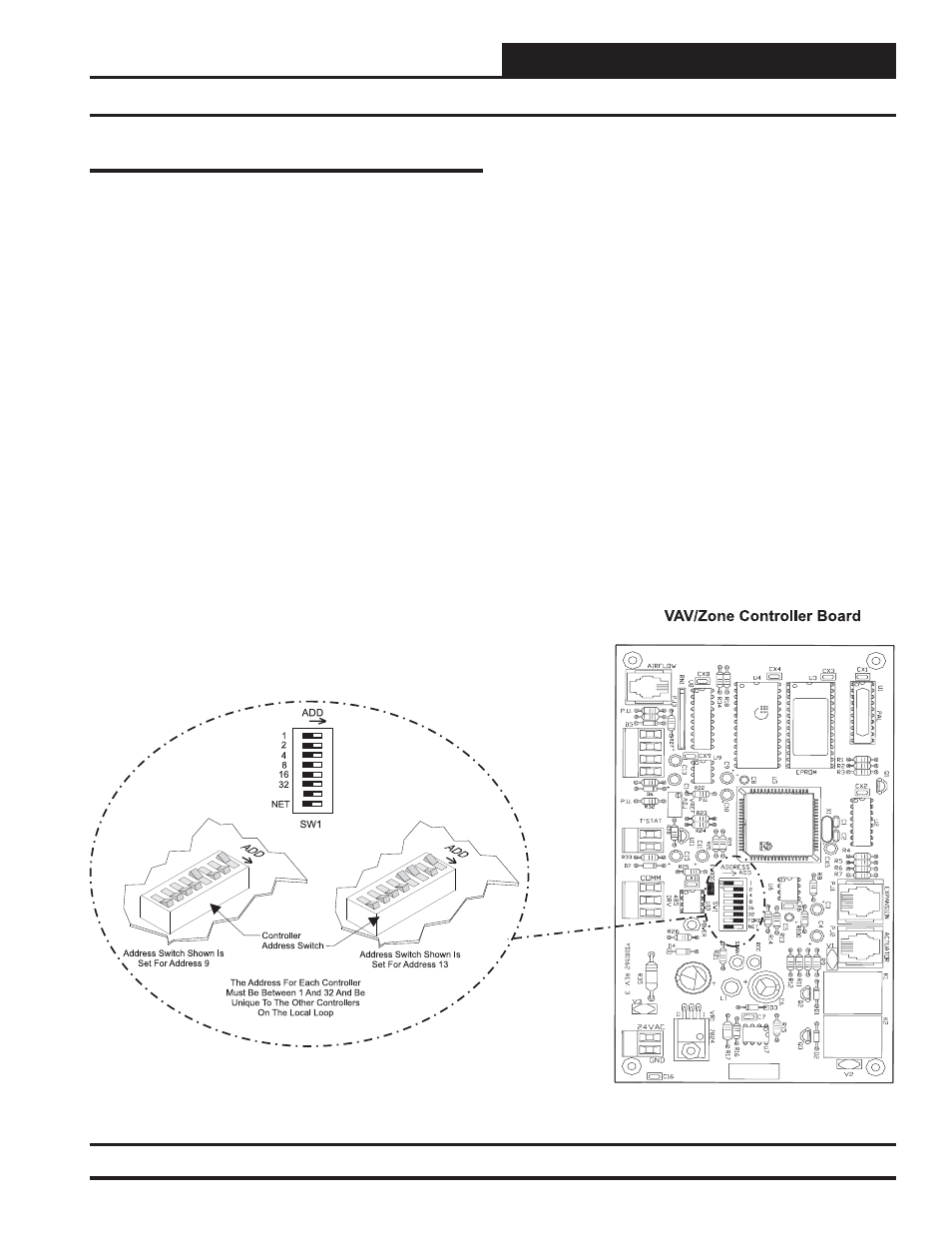
Figure 10: Address Switch Setting
Check that the Room Sensor connector is connected to one end of the
sensor and the other end is connected to the sensor connector on the
VAV/Zone Controller board. Be sure any Expansion Boards connected
to the VAV/Zone Controller are also correctly wired per the Expansion
Board wiring instructions on pages 7 through 13 of this manual.
After all the above wiring checks are complete, apply power to the VAV/
Zone Controller(s).