I. introduction – WattMaster WM-WCC3-TGD-01B User Manual
Page 36
I. INTRODUCTION
WCC III Technical Guide
I-14
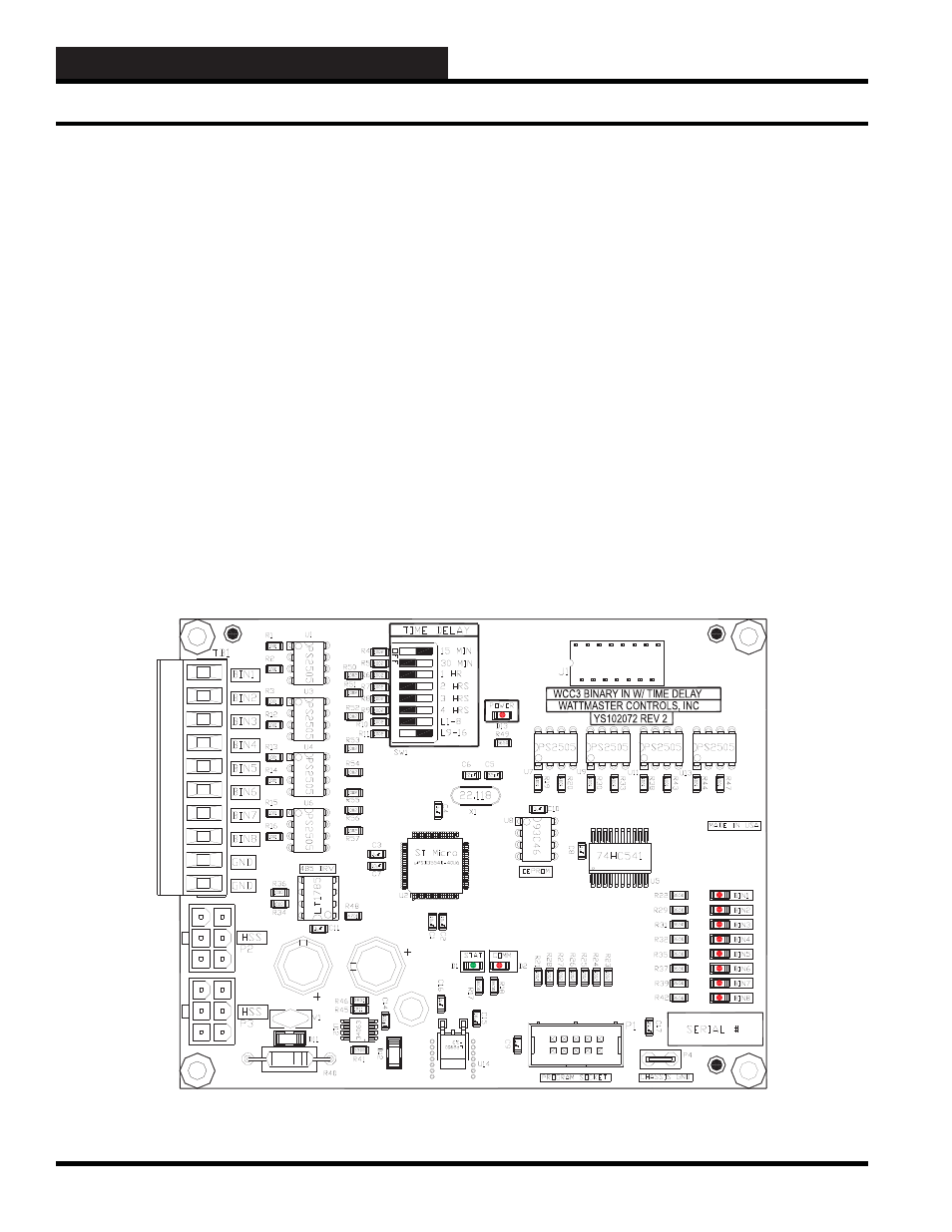
Accessory Boards - Binary Input with Time Delay
OPTIONAL WCC III ACCESSORY
BOARD TYPES
WCC III Binary Input with Time Delay
Board - (OE431-01) (SS5006)
The new WCC III Binary Input with Time Delay Board provides a
terminal point for landing wire for an external input switch / relay
contact. It can interface to the SAT II or SAT III Controller via a
16-pin ribbon cable with “DIP” connectors on both sides.
Connect “J1” on the WCC III Binary Input with Time Delay Board
to one of the two removable DIP SWITCHES on the cover of
the SAT II or SAT III Controller. These two switches are labeled
Binary Inputs on the cover of the SAT II or SAT III Controller. An
alternative method of connection to only the SAT III Controller is
provided by the 6-pin HSS communications port on the side of the
SAT III Controller. This HSS communications port does not exist
on the SAT II Controller.
The eight Binary Inputs on the new WCC III Binary Input with
Time Delay Board are dry contact closures to ground only. See
Section 17 for specifi c use and application of the WCC III Binary
Input with Time Delay Board.
The WCC III Binary Input with Time Delay Board has 11 status
lights. The functions of these lights or LEDs are listed below.
•
STAT
- This LED blinks for every second if WCC III
Binary Input with Time Delay board is alive.
•
PWR
- This LED will be lit any time power is applied to
the WCC III Binary Input with Time Delay board.
•
COMM
- This LED will be lit when communications are
being received by the WCC III Binary Input with Time
Delay board.
•
BIN 1 to BIN 8
- These eight LEDs will be lit anytime
a corresponding pulse is detected on the eight inputs of
WCC III Binary Input with Time Delay board.
Figure I-9: The WCC III Binary Input with Time Delay Board