Wcc iii installation guide, Sat iii relay outputs, Wcc iii technical guide 12-21 – WattMaster WM-WCC3-TGD-01B User Manual
Page 517: Sat iii, Hc com
12. WCC III INSTALLATION
GUIDE
WCC III Technical Guide
12-21
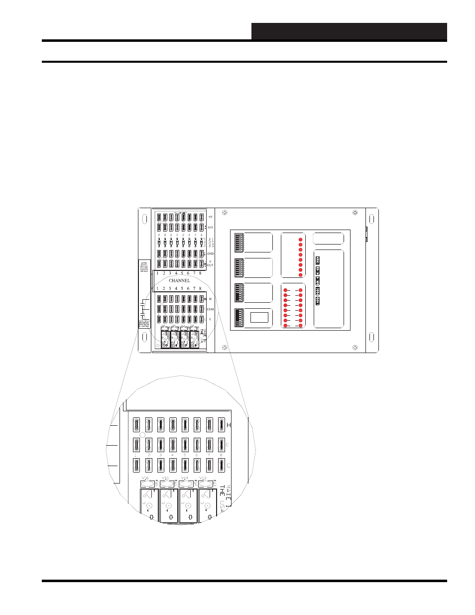
SAT III Relay Outputs
The standard SAT III controller is capable of providing 16 binary
(on/off) relay outputs. These 16 relay outputs are for driving pilot
duty relays. There is a load protection device called a varistor
across each of the 16 output connections that limits the allowable
voltage to no more than 32 volts AC\DC maximum at 1.0 or 1 amp
current draw for each contact.
8
7
SAT ADDRESS
2
1
4
8
A 3 WIRE ROOM SENSOR WILL NOT
REQUIRE A LOAD RESISTOR WHEN SET
FOR A 1 VOLT INPUT.
WattMaster Controls Inc.
BINARY
INPUTS
BINARY
INPUTS
L8
ON OFF
128
32
16
64
L4
L3
L2
L1
L6
L5
L7
L11
L12
ON OFF
L10
L9
ON OFF
L15
L16
L14
L13
C
H
4
3
5
6
2
1
LOCAL SET
STATUS 2
STATUS 3
STATUS 1
HSS XMIT
LOCAL SET
LOCAL SET DISABLE
BATT ON/ OFF
PULSE INPUT
OPTION 1
TEST
OPTION 3
OPTION 2
ON OFF
STATUS
HSS REC
SAT XMIT
SAT REC
ANALOG INPUT
JUMPER SELECTION
A 2 WIRE ROOM SENSOR WILL REQUIRE
A 300 OHM LOAD RESISTOR WHEN SET
FOR A 1 VOLT INPUT.
A 4 TO 20 mA SENSOR WILL REQUIRE A
50 OHM LOAD RESISTOR WHEN SET FOR
A 1 VOLT INPUT, OR A 250 OHM LOAD
RESISTOR WHEN SET FOR A 5 VOLT INPUT.
CURRENT
INPUT
THERMISTOR
INPUT
0 - 1V
0 - 5V
0 - 10V
THERM
0 - 1V
0 - 5V
0 - 10V
THERM
0 TO 10V
INPUT
0 TO 5V
INPUT
0 TO 1V
INPUT
0 - 10V
0 - 1V
0 - 5V
0 - 10V
THERM
0 - 1V
0 - 5V
THERM
0 - 1V
0 - 5V
0 - 10V
THERM
PROGRAMMABLE CONTROLLER
SAT III
H
C
COM
CHANNEL
2
1
3 4 5 6 7 8
10A
25
0V
A
C
~
5A
3
0
V
D
C
SA
VDE
G5
Q-
1
A
4
OMR
O
N
DC
2
4
V
CH
IN
A
1
0
A2
5
0
VAC
~
5A
30V
D
C
SA
VD
E
G5
Q-
1
A
4
OMR
O
N
D
C
24V
CHI
N
A
10A
25
0
V
A
C
~
5A
30V
D
C
SA
VD
E
-1A
4
ON
24V
CH
IN
A
10A
25
0V
A
C
~
5A
3
0
V
D
C
SA
VD
E
G5
Q-
1
A
4
OM
R
O
N
D
C
24V
CHI
N
A
NTACT
FOR
VDC
AX
Figure 12-17: SAT III “H” and “C” control output wiring connections
Attempting to switch any voltage greater than 32 Volts, or current
draws of more than 1.0 or 1 amp per contact could and will result
in damage to the SAT III controller. These “H” and “C” contact
outputs are meant to control tri-state actuators, contactors, relays,
solenoids, and the PI board AKA “ECC II ANALOG OUTPUT”
board that WattMaster Controls used to manufacture. These relay
outputs can be programmed in three different types of modes of
basic operation: Time Clock, Dual Limit, and EA Mode. See
Section 3 for further details on Satellite programming instructions.
SAT III Relay Outputs