Fig. 24.12 – Westermo RedFox Series User Manual
Page 577
Advertising
Westermo OS Management Guide
Version 4.17.0-0
FRNT
+DC1
+DC2
COM
COM
ST1
ST2
ON
DC1
DC2
1
2
POWER
CONSOLE
IO
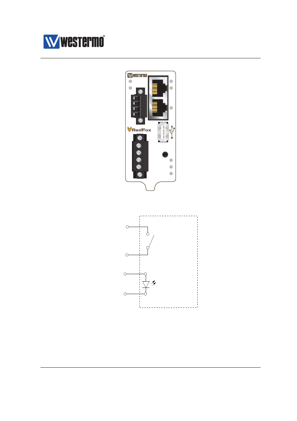
Figure 24.12: The Power and CPU module of a RedFox Industrial unit
Digital In+
Digital In−
Digital Out−
Digital Out+
No. 1
No. 2
No. 4
No. 3
Westermo switch
As described in
, Digital-In can be used as an alarm source, while
Digital-Out is utilised as an alarm target (summary alarm).
❼ The Digital-In alarm is triggered when there is lack of voltage on the Digital-
In pins. For information on appropriate voltage/current levels to trigger
➞ 2015 Westermo Teleindustri AB
577
Advertising
This manual is related to the following products: