Figure 3-92 switched carrier, spectrum view, Figure 3-93 switch event, event log – Comtech EF Data VMS v3.12.x Vipersat User Manual
Page 186
Network Manager Configuration
MN/22156, rev 12
3-86
VMS User Guide
Review the configuration procedure to identify and correct the mistake. If
unable to resolve the situation, contact Comtech Vipersat Networks
Customer Support for assistance (see “Contact Information” on page 1-15).
4. Observe the change in the Spectrum View (figure 3-92); a blue shaded area
will appear representing the slot assigned by the VMS for the switch. Upon
receipt of the next PLDM (Path Loss Data Message), the carrier(s) will
appear showing the current E
b
N
0
and bandwidth.
For P2P switching, two separate carriers (Tx and Rx) will appear for that
site, as shown in this example.
Figure 3-92 Switched Carrier, Spectrum View
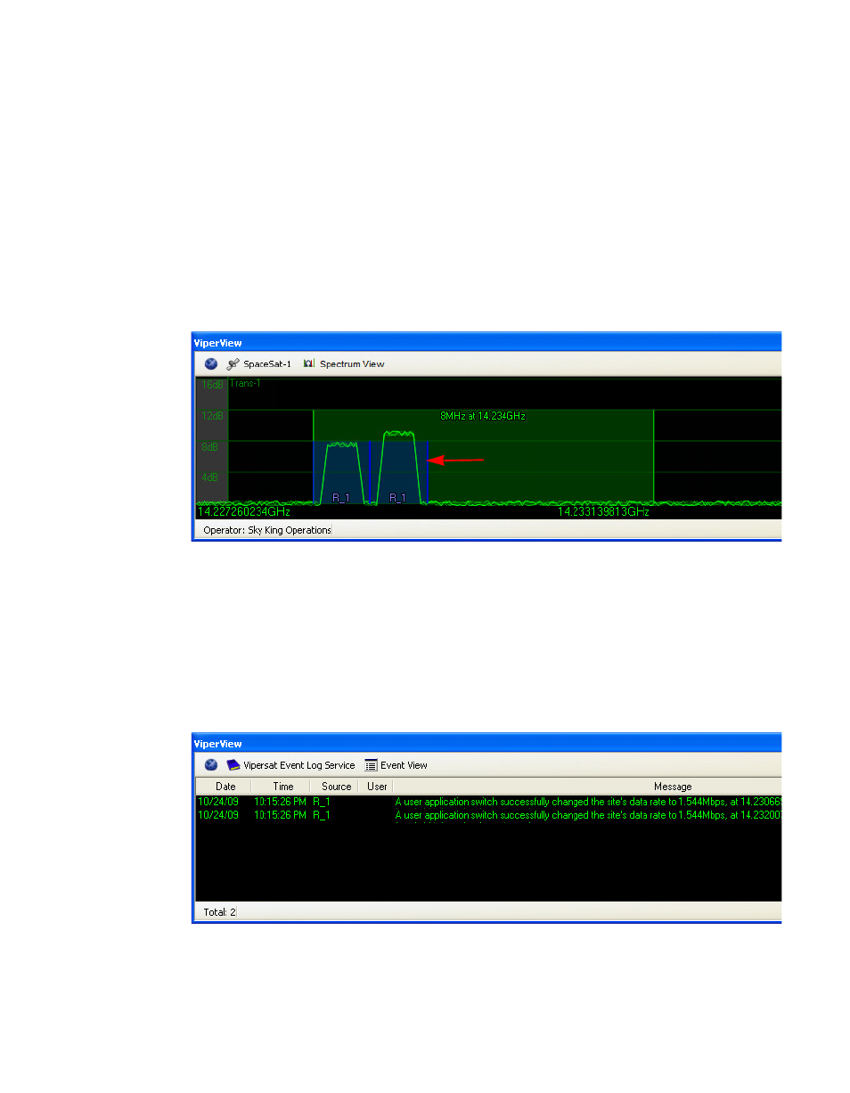
5. Also, note the new entry in the Event View stating that the application switch
was successful with the new data rate and frequency (figure 3-93).
For a Remote site that is configured for P2P switching, two entries will
appear in the Event View: the first entry relates to the Remote modulator’s
Tx rate, and the following entry relates to the Remote demodulator’s Rx rate.
Figure 3-93 Switch Event, Event Log