Figure 4-25 link adaptation configuration, cdm – Comtech EF Data VMS v3.12.x Vipersat User Manual
Page 256
Network
MN/22156, rev 12
4-38
VMS User Guide
Bit rate = Symbol rate * Modulation order * Code rate
To ensure that the bandwidth allocated for a particular link is never exceeded,
the symbol rate (and power) must remain constant. Therefore, this equation
demonstrates that the bit rate increases with a higher ModCod, and decreases
with a lower ModCod.
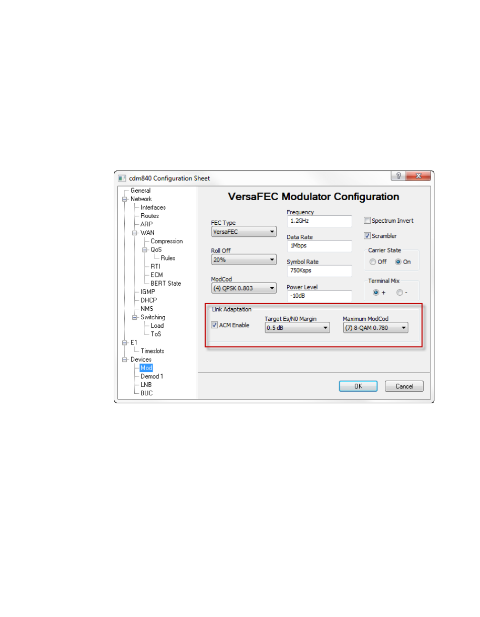
Note that the Link Adaptation configuration for the CDM-840 Remote unit is
done from the VersaFEC Modulator dialog (figure 4-25). See section
“Devices | Mod” on page 4-58 for more information on setting the ACM param-
eters for the Remote unit.
Figure 4-25 Link Adaptation Configuration, CDM-840
Clicking on the ACM menu item for the CDD-880 displays the Link Adaptation
dialog shown in figure 4-26.
A table listing the Demods (maximum of 12) for the router provides the means
to Enable or Disable ACM for each one individually. Select the desired Demod
and click the Modify button to change the current setting.
In a VMS managed network, the IP Address of the Remote is automatically
assigned based on dynamic switching operations (dSCPC). When a demod has
been assigned to receive communications from a CDM-840 transmitter due to a
dynamic switch, the Remote IP Address field will display the address of the