Figure c-40 buc configuration, cdm-570/570l, Figure c-41 lnb configuration, cdm-570/570l – Comtech EF Data VMS v3.12.x Vipersat User Manual
Page 449
Appendix
C -
Redundancy
C-39
MN/22156, rev 12
N:M Hub Modem Redundancy
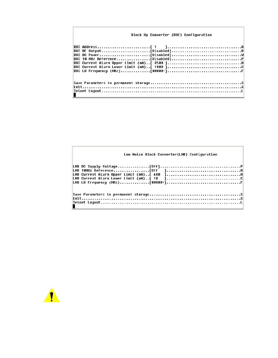
Figure C-40 BUC Configuration, CDM-570/570L
11. On the
Satellite Modem Configuration > Configuration > Low Noise
Block Converter (LNB) Configuration
page, disable the LNB DC Supply
Voltage by setting it to [Off], as shown in figure C-41.
Figure C-41 LNB Configuration, CDM-570/570L
12. This completes the process of setting the modem/router to parked configu-
ration mode, and it is now ready to be put back into service.
13. If the repaired unit is to be connected to the same plug, it will automatically
reinstate the unit as a member of the backup group. VMS identifies the unit
by its MAC address so if, for any reason, the failed unit is replaced with
another unit, you will have to go to VMS and drag the newly installed unit to
the appropriate plug on the power strip to complete its installation.
Caution: Failure to follow the discipline of connecting the repaired unit to the
correct plug on the remote controlled power strip will result in the unit
not being able to be turned off if it fails while acting as the primary
unit, resulting in the possibility of having two active units trying to
operate in the same role and consequently crashing the network.