Load switch example, Load switch example . . . . . . . . . . . e-13, Figure e-7 load switching diagram – Comtech EF Data VMS v3.12.x Vipersat User Manual
Page 469
Appendix E - Automatic Switching
E-13
MN/22156, rev 12
Load Switching
Load Switch Example
An automatic load switching example, illustrated in the schematic diagram in
figure E-7, illustrates how a network can respond to changes in traffic volume
or load conditions. The network’s capability and method of response to load
changes is determined by the setting and capability of each of the components in
the system, such as the transmitter power output, the antenna capabilities for
each of the sites in the network, and the policies set in the VMS.
The elements for determining policies and their interactions are covered in this
section.
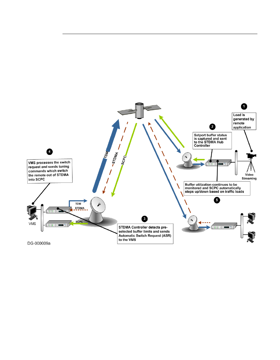
Figure E-7 Load Switching diagram
A load switch is illustrated in figure E-7 using the following process:
1.
A load is generated by an application that is running at a Remote. In this
example, the application is a video stream.
2. The data is connected to the Remote modem/router over an Ethernet link for
transmission to the satellite. While the data-stream transmission is in prog-
ress, the Satport buffer status is captured and the Remote’s buffer status is
sent to the STDMA Hub Controller.