Figure 3-37 binding demodulator to down, Converter, Figure 3-38 stdma and tdm carrier appearance – Comtech EF Data VMS v3.12.x Vipersat User Manual
Page 139
Chapter
3 -
VMS Configuration
3-39
MN/22156, rev 12
RF Manager Configuration
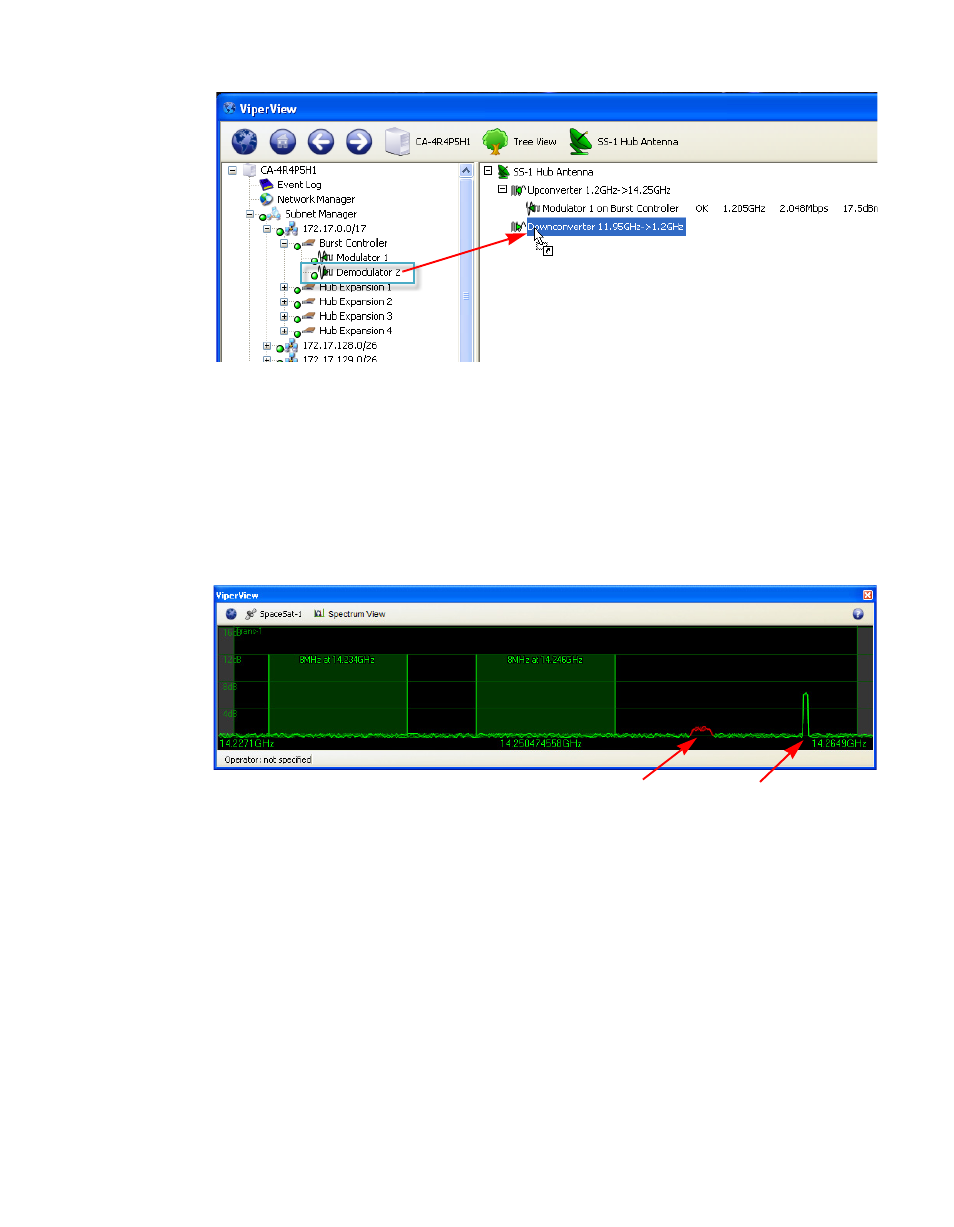
Figure 3-37 Binding Demodulator to Down Converter
As soon as the Hub BC binding is complete, the STDMA and the TDM carriers
will appear in the Spectrum view. Note that the TDM carrier is displayed in red
due to the fact that a power value has not yet been reported from a receiving
Remote. The STDMA carrier appearance will vary between green and red, as
the accuracy of the Eb/No values received by the BC may fluctuate due to the
rapid locking/unlocking behavior.
Figure 3-38 STDMA and TDM Carrier Appearance
5. Repeat the above steps for each additional unit at this site.
Now that the binding procedure for the first unit has been completed with the
understanding of the relationship between the modem devices and the
converters, perform all subsequent bindings by simply dragging the modem
unit and dropping it directly onto the antenna. This abbreviated method will
automatically bind the mods and demods with the up converters and down
converters.
6. Select the next site antenna and perform the binding procedure for the units
at that site.
TDM Carrier
STDMA Carrier