Figure 7-26 select return path demodulator, Custom – Comtech EF Data VMS v3.12.x Vipersat User Manual
Page 386
Switching Out-of-Band Modems
MN/22156, rev 12
7-30
VMS User Guide
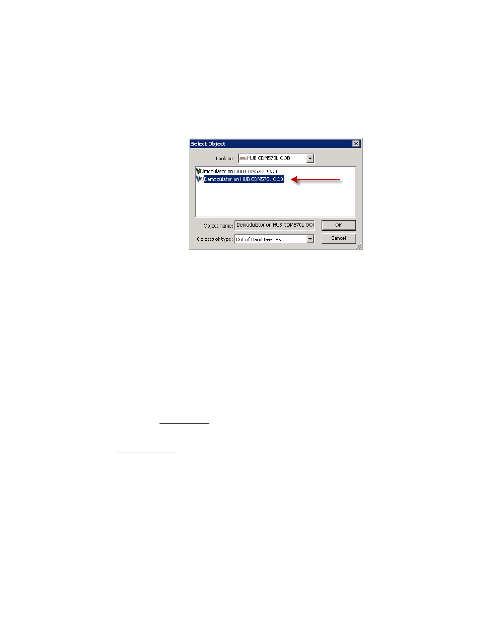
Click on the Managed Device bar to select the next managed device (for the
second channel). In the example used here, this will be the demodulator at
the Hub. It can be associated with the same modem from which the
modulator was selected, or from another available unit.
14. Again, navigate the Select Object window and select the target device, as
shown in figure 7-26.
Figure 7-26 Select Return Path Demodulator, Custom
15. Enter the parameter settings for this channel:
•
Ideal and Minimum Bit Rates
•
Power required to establish the link
•
Priority level (if applicable)
•
FEC and Modulation (if applicable)
16. Add the Unmanaged Device(s) for this channel.
For this example, the Remote 8 OOB modulator.
If this is the last channel required for the circuit that is being created, continue
with the next step.
If more channels remain to be defined for this circuit, repeat the procedure from
17. Click on the Next button (becomes active when configuration parameters
have been set) to proceed to the wizard Summary Page (figure 7-28).
Carefully review all information on this page prior to proceeding. The Back
button is available to retrace the configuration and make any changes that
might be necessary before final circuit creation.