Figure c-9 n:m redundancy logic diagram, Appendix, Redundancy – Comtech EF Data VMS v3.12.x Vipersat User Manual
Page 425
Appendix
C -
Redundancy
C-15
MN/22156, rev 12
N:M Hub Modem Redundancy
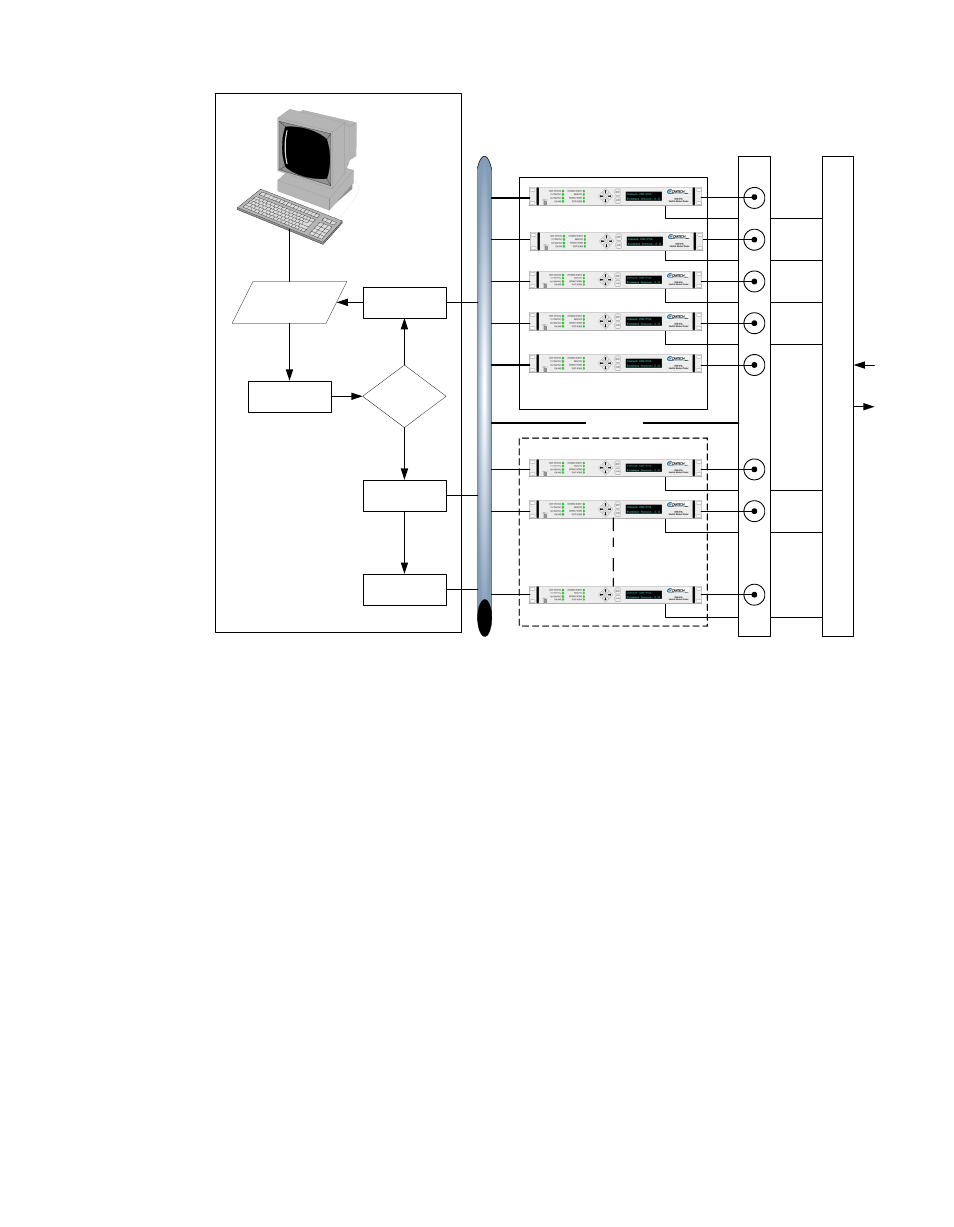
Figure C-9 N:M Redundancy Logic Diagram
The switching control mechanism is completely monitored and controlled by
the host master processing VMS as shown in the logic diagram in figure C-9.
The VMS parameter backup and restore function is used to copy each primary
unit’s configuration database information which is then stored in a lookup list.
The stored primary unit’s parameter files are used to put the image of a failed
primary unit’s parameters into a standby spare unit. The spare units should
always be in the parked configuration described in the section “Setting Unit to
Parked Configuration Mode” on page C-35, powered on, and listening and
responding to the local LAN network.
After the N:M redundancy has been installed, as described in the section
“Installing N:M Redundancy” on page C-16, the VMS starts listening for heart-
beat messages from each of the primary and backup spare units for health and
fault code response as shown in the logic diagram in figure C-9. If any primary
unit fails (has an alarm set, or fails to send a heartbeat within the Timeout
parameter setting in Vipersat Manager), the VMS will invoke the backup proce-
dure by sending a copy of the failed unit’s database to the next available standby
spare.
ET
HER
N
ET
Spares Backup
N Spares
Primary Units
SNMP IP
Network Controlled
AC Power Bus
RF
C
ombine
r/
S
plitt
e
r
Primary
Parameter
List
Status
Watchdog
Parameter
Copy
AC Power
Control
Poller
N to N Redundancy Process
OK
OK
Fault
VMS