Oob circuit operations, Viperview circuit operations, Oob circuit operations -32 – Comtech EF Data VMS v3.12.x Vipersat User Manual
Page 388: Viperview circuit operations -32, Figure 7-29 circuit list
Switching Out-of-Band Modems
MN/22156, rev 12
7-32
VMS User Guide
If the configuration is accepted by the wizard, the page will indicate that the
Circuit Creation Succeeded, accompanied by a green check mark. Click on the
Close button to exit the wizard.
A red check mark will indicate if the Circuit Creation Failed. Note that a
common configuration error that will cause this result is failing to associate the
devices (modulator and demodulator) of the modem unit with the converters for
the site antenna(s). Identify and correct the cause of the error, then rerun the
circuit creation wizard.
OOB Circuit Operations
Once the circuits have been configured, there are 3 methods available for
executing Setup and Takedown operations:
• ViperView
• ArrangeLink
• VNO
OOB switch events are recorded in the Event Log. Every switch—both setup
and takedown—will log one event for the circuit plus an event for each channel
associated with that circuit.
ViperView Circuit Operations
Using the ViperView interface, the operator can view the circuits and choose
from several commands to execute the desired operation. Circuits can be viewed
from the owning site (the site from which they were created) as well as from the
group level and the network level. At the network level, all circuits defined
within that network will appear. Right-click on either the site, group, or network
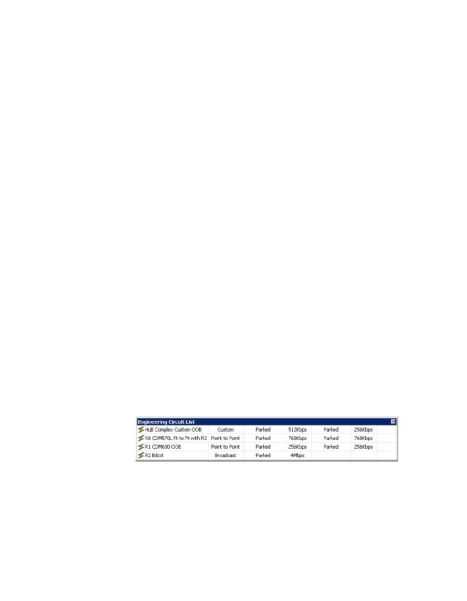
icon and select Show OOB Circuits from the drop-down menu. The Circuit
List window will open, as shown in figure 7-29.
Figure 7-29 Circuit List
Right-clicking on a circuit will display the operations command menu