Figure 3-94 switched carrier, hub antenna view – Comtech EF Data VMS v3.12.x Vipersat User Manual
Page 187
Chapter
3 -
VMS Configuration
3-87
MN/22156, rev 12
Network Manager Configuration
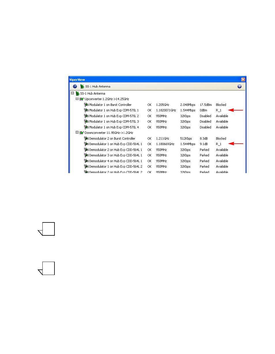
6. From the Tree View, click on the Hub antenna under the Network Manager
to display the Hub devices in the right window panel.
From this view, the operator can see the switched modulator and
demodulator that the VMS selected for this session, the carrier frequency in
L-Band, the bit rate, the current E
b
N
0
, and the identity of the Remote site
Figure 3-94 Switched Carrier, Hub Antenna View
7. End the session by selecting its appearance in the Application Sessions
window and clicking on the Takedown button.
Note: After reaching this point and all indications are as noted above, the
Vipersat Manager, the RF Manager, and the Network Manager have
been configured successfully. All frequencies and conversions are
correct. To test the policies, it will be necessary to set up an application
such as VoIP.
Note: Additional (or all) Remote sites can be created and InBanded using the
manual method described up to this point. However, it is recommended
that, once the initial Remote site has been configured and can be used
as a template reference, the remaining Remote sites be generated by
utilizing the Remote Site Wizard feature as described below.
NOTE
NOTE