Sample installation, Sample installation . . . . . . . . . . c-18, Figure c-10 n:m block diagram – Comtech EF Data VMS v3.12.x Vipersat User Manual
Page 428
Advertising

N:M Hub Modem Redundancy
MN/22156, rev 12
C-18
VMS User Guide
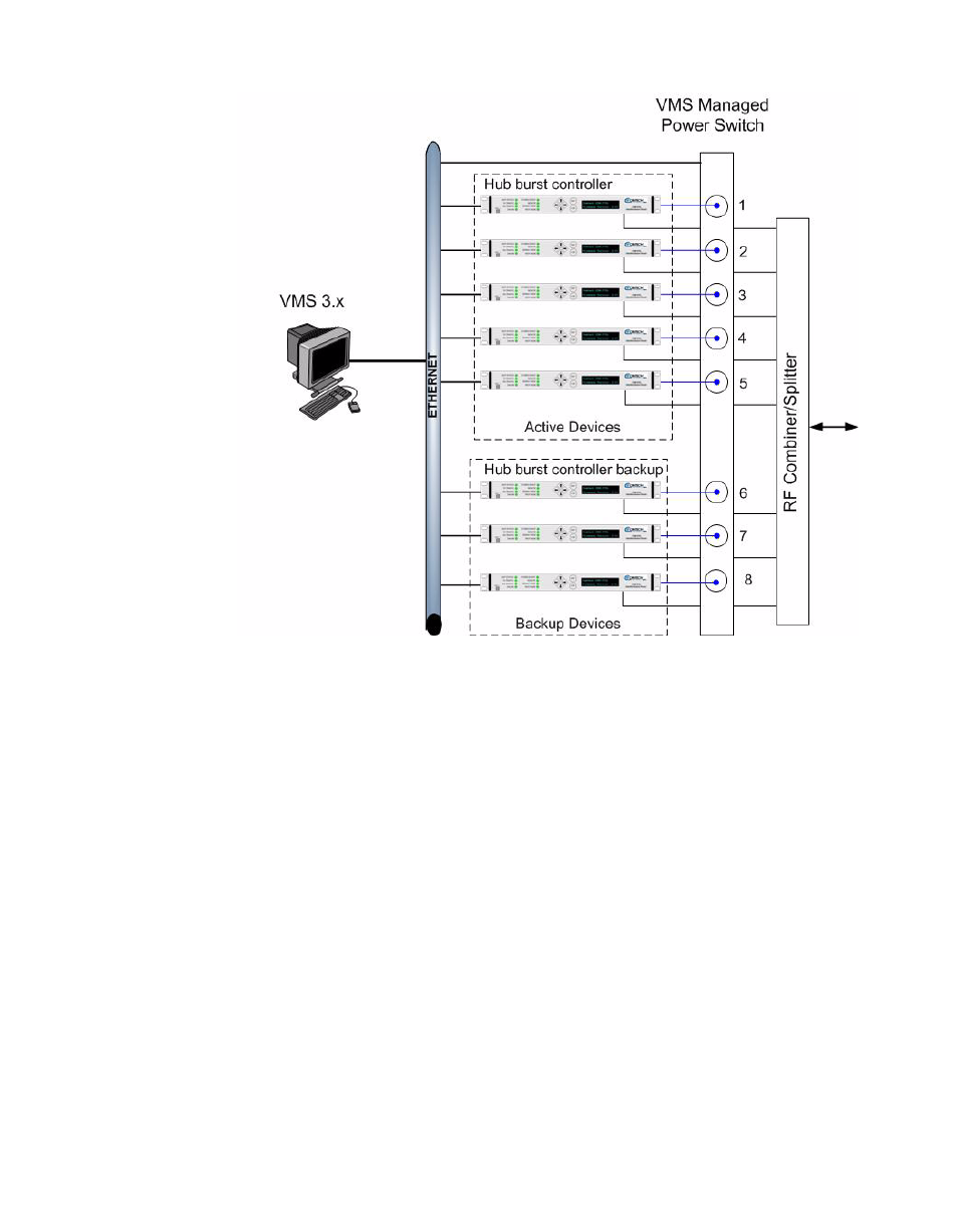
Figure C-10 N:M Block Diagram
Sample Installation
Figure C-11 shows a diagram of a sample installation of an N:M redundant
VMS installation. As shown in figure C-11, the units in the primary and second-
ary groups share a common Ethernet LAN with the IP controlled power switch.
Advertising