Figure c-11 typical n:m redundant installation, The url, Appendix – Comtech EF Data VMS v3.12.x Vipersat User Manual
Page 429: Redundancy, C-19
Appendix
C -
Redundancy
C-19
MN/22156, rev 12
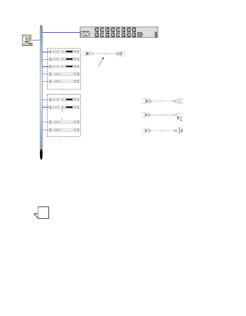
N:M Hub Modem Redundancy
Figure C-11 Typical N:M Redundant Installation
The URL
http://www.servertech.com/documents
provides the Power Tower XL/
XM Installation and Operation manuals (in PDF form) for the network
controlled power strip shown in figure C-11. Refer to these manuals for detailed
information on this device.
Note: All units in both the primary and secondary group must be identical, with
exactly the same hardware configuration and accessories, and have
identical firmware revision levels.
Use the following procedure to implement the optional N:M capability in a
VMS network.
ET
HER
N
E
T
Spares Backup
N
Spares
Primary Units
VMS
IP Network Controlled A/C Power Strip
International Model
230 VAC, 50/60 Hz
CVNI P/N: PWRTWR-H-INTL-16
Modem-to-Power Tower Cord
CVNI P/N 22220
Power Tower to A/C Mains Cord
CVNI P/N 22223
Europe
Power Tower to A/C Mains Cord
CVNI P/N 22224
United Kingdom
Power Tower to A/C Mains Cord
CVNI P/N 22225
Australia
SNMP IP
Input
Current
Serial
Ethernet
NOTE