Vms operation & architecture, Vms operation & architecture -9, Figure 1-2 viperview client / server (vos) – Comtech EF Data VMS v3.12.x Vipersat User Manual
Page 33: Relationship
Chapter
1 -
General
1-9
MN/22156, rev 12
Product Description
VMS Operation & Architecture
A Vipersat network provides Internet Protocol (IP) connections between
network nodes and supporting UDP and Multicast protocols. Vipersat satellite
networks rely on Vipersat modem/routers to provide the interface between LAN
traffic and the satellite links that connect Remote stations to the Hub.
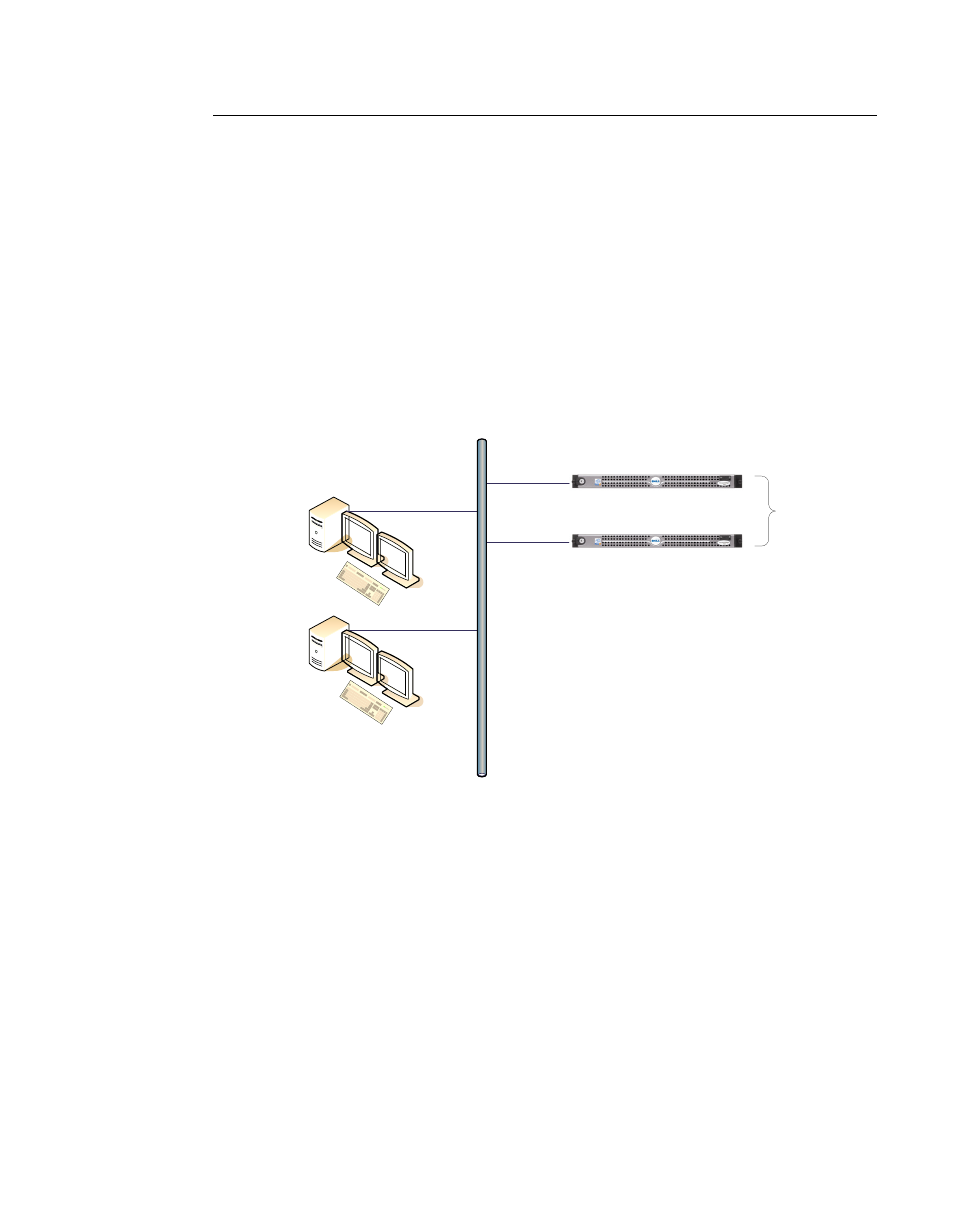
The VMS Client (ViperView) and Server (Vipersat Object Service) architec-
ture (figure 1-2) supports centralized management, control, and distribution of
data, alarms, and events. Network units, such as a Vipersat modem/router, while
functioning as a modulator/demodulator, also detect, analyze, and report details
on network operation to the VMS. The VMS collects, stores, analyzes, and acts
on this information to intelligently control network operation to optimize band-
width utilization and overall network performance.
Figure 1-2 ViperView Client / Server (VOS) Relationship
The VMS management and monitoring system uses an intuitive graphic display,
as illustrated in figure 1-1. The VMS makes visible the entire network’s opera-
tion and performance. All network status and performance data is collected,
processed, and stored at the server. Any client workstation can retrieve informa-
tion from the VMS server’s single, central database.
The VMS network management system displays the following information
gathered from the network modem/routers:
• System configuration
• Transmission configurations
VMS
Client
ViperView
VMS
Vipersat Object Service
(VOS) Server
VMS
Vipersat Object Service
(VOS) Server
VMS
Client
ViperView
Redundant VMS
Servers