Half duplex circuit configuration, Half duplex circuit configuration -20 – Comtech EF Data VMS v3.12.x Vipersat User Manual
Page 376
Switching Out-of-Band Modems
MN/22156, rev 12
7-20
VMS User Guide
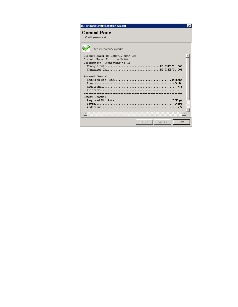
Figure 7-15 Commit Page, Full Duplex P2P
A red check mark will indicate if the Circuit Creation Failed. Note that a
common configuration error that will cause this result is failing to associate the
devices (modulator and demodulator) of the modem unit with the converters for
the site antenna(s). Identify and correct the cause of the error, then rerun the
circuit creation wizard.
Half Duplex Circuit Configuration
Half Duplex broadcast circuits are defined by the device (modulator or demodu-
lator) and consist of one channel or multiple channels. By design, the managed
device will be the modulator and there will only be one modulator per circuit.
The circuit must be created on the site with the modulator as it will be the source
of all outgoing traffic.
1.
Right-click on the site icon that will be the transmitting source for the
broadcast and select Create OOB Circuit from the drop-down menu to
open the Circuit Creation Wizard. The Circuit Identification dialog will
appear, as shown in .figure 7-16.