Setting up n:m redundancy, Setting up n:m redundancy . . . . . . . c-20, Figure c-12 n:m redundancy hierarchy – Comtech EF Data VMS v3.12.x Vipersat User Manual
Page 430: Figure c-13 redunancy manager tree
Advertising
N:M Hub Modem Redundancy
MN/22156, rev 12
C-20
VMS User Guide
Setting Up N:M Redundancy
There are 3 hierarchal objects in N:M Redundancy, as shown in figure C-12.
They are:
1.
Redundancy Manager
2. Containers
3. Power Strips and Groups
Figure C-12 N:M Redundancy Hierarchy
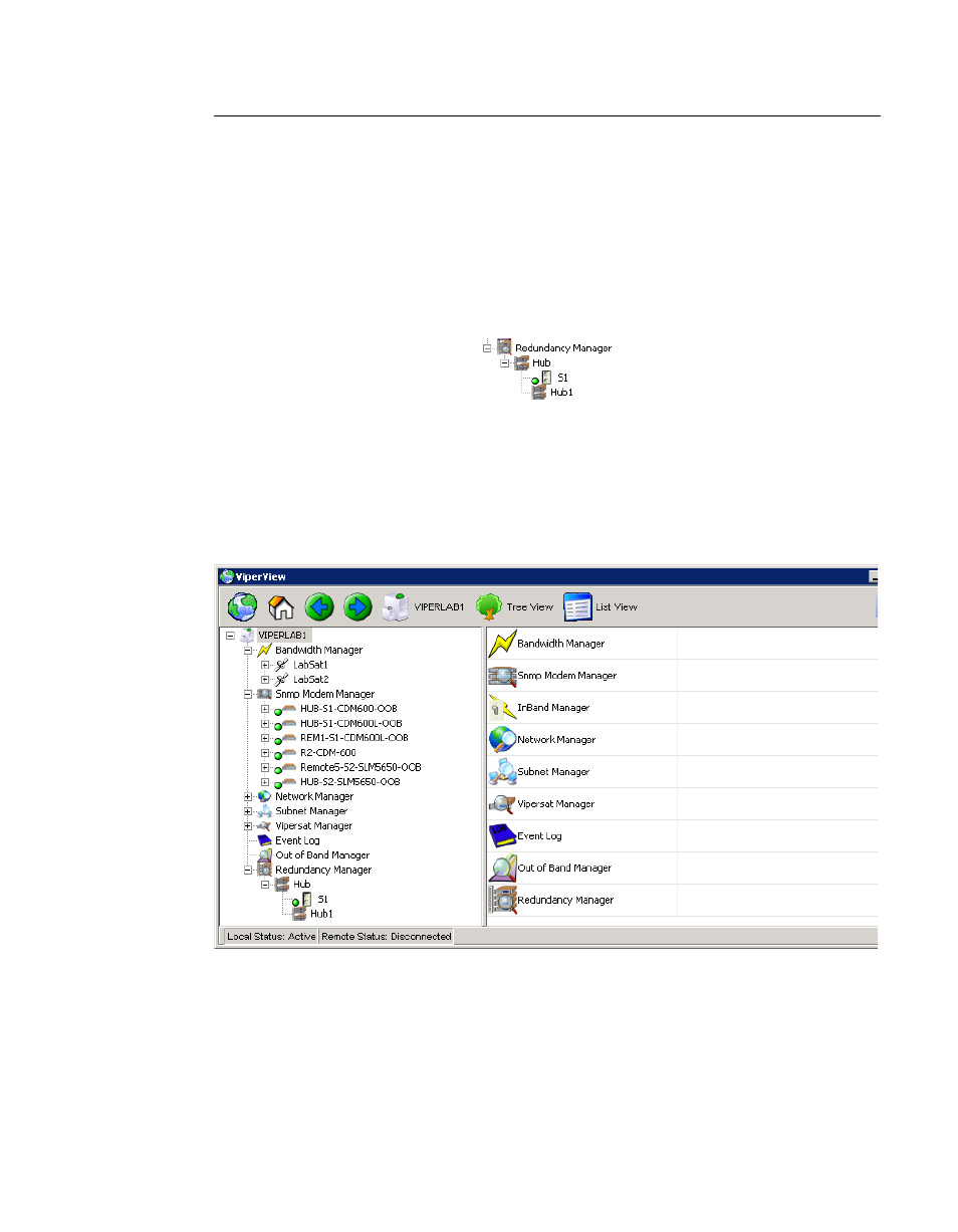
Expanding the Redundancy Manager icon, shown in figure C-13, shows a typi-
cal N:M redundancy installation. Under the Redundancy Manager service icon
are the icons for a container named Hub, in this example.
Figure C-13 Redunancy Manager Tree
Expanding the Hub icon shows additional icons such as the remote controllable
switch labeled S1 in this example, and a group labeled Hub1.
Advertising