Refer to, Figure, Connect control wires as shown in – Yaskawa Z1000U HVAC Matrix Bypass User Manual
Page 103: Figure 3.31, Figure 3.32, 5 control circuit wiring
A
B
C
D
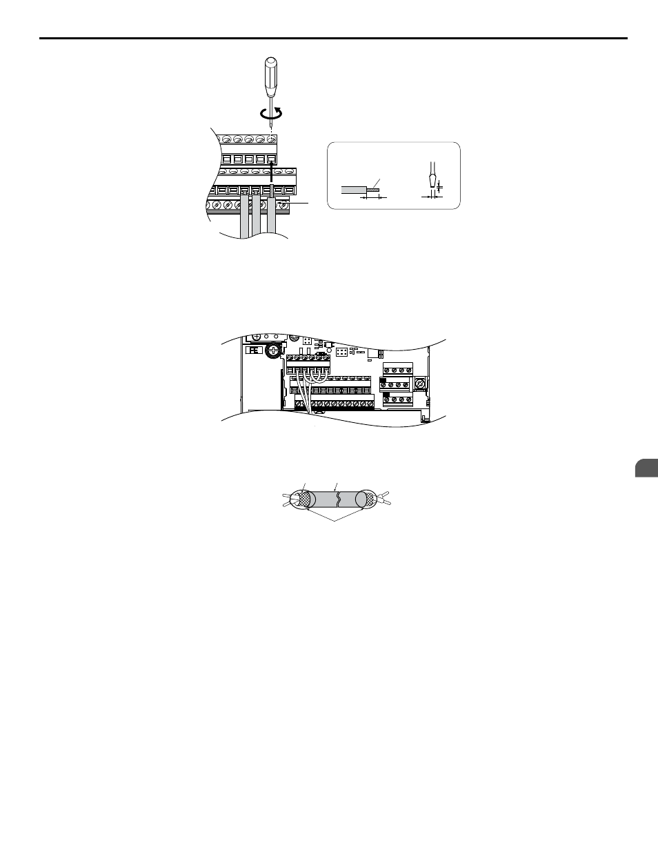
Preparing wire
terminal ends
A – Loosen screw to insert wire.
B – Single wire or stranded wire
C – Avoid fraying wire strands when
stripping insulation from wire. Strip
length 5.5 mm.
D – Blade depth of 0.4 mm or less
Blade width of 2.5 mm or less
Figure 3.31 Terminal Board Wiring Guide
E(G) IG R+ R- S+ S-
S1 S2 S3 S4 S5 S6 S7 S8 SN SC SP
V+ AC A1 A2 A3 FM AM AC
24V
RP AC
M1 M2 M3 M4
MD ME MF
MA MB MC
TB5
Figure 3.32 Terminal Board Location Inside the Drive
A
E
B
C
D
A – Drive side
B – Insulation
C – Control device side
D – Shield sheath (insulate with tape)
E – Shield
Figure 3.33 Preparing the Ends of Shielded Cables
NOTICE: The analog signal wiring between the drive and the operator station or peripheral equipment should not exceed 50 meters when
using an analog signal from a remote source to supply the frequency reference. Failure to comply could result in poor system performance.
3.5 Control Circuit Wiring
YASKAWA SIEP YAIZ1D 01A Z1000U HVAC MATRIX Drive Bypass Technical Manual
103
3
Electrical Installation