H: terminal functions, H1: multi-function digital inputs, 7 h: terminal functions – Yaskawa Z1000U HVAC Matrix Bypass User Manual
Page 165
5.7 H: Terminal Functions
H parameters assign functions to the external terminals.
u
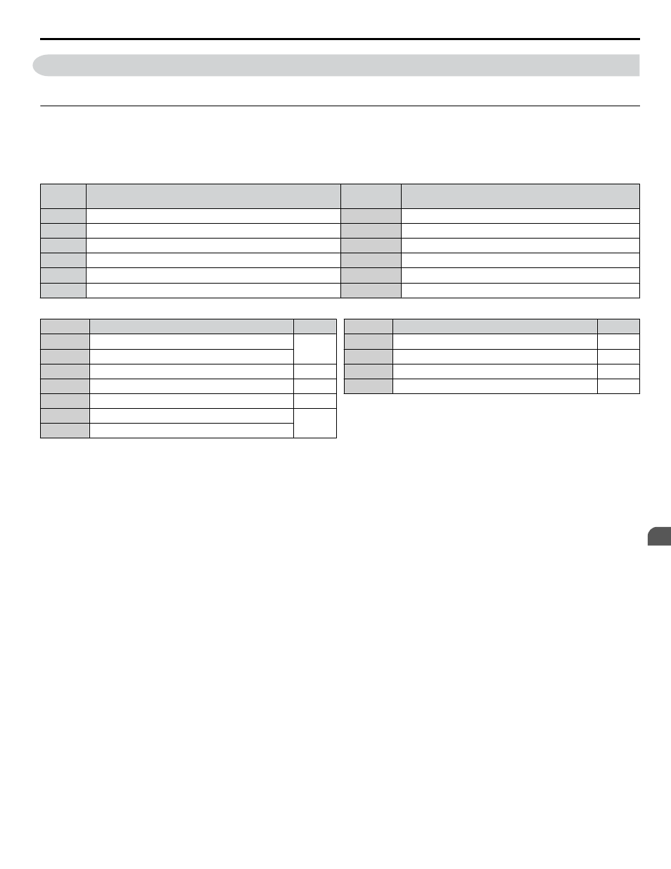
H1: Multi-Function Digital Inputs
n
H1-03 to H1-08: Functions for Terminals S3 to S8
.
No.
Parameter Name
Setting
Range
Default
H1-03
Multi-Function Digital Input Terminal S3 Function Selection
3 to 60
24: External Fault
H1-04
Multi-Function Digital Input Terminal S4 Function Selection
3 to 60
14: Fault Reset
H1-05
Multi-Function Digital Input Terminal S5 Function Selection
3 to 60
3: Multi-Step Speed Reference 1
H1-06
Multi-Function Digital Input Terminal S6 Function Selection
3 to 60
4: Multi-Step Speed Reference 2
H1-07
Multi-Function Digital Input Terminal S7 Function Selection
3 to 60
F: Not Used (Through Mode)
H1-08
Multi-Function Digital Input Terminal S8 Function Selection
3 to 60
F: Not Used (Through Mode)
Table 5.21 Multi-Function Digital Input Terminal Settings
Setting
Function
Page
3
Multi-Step Speed Reference 1
4
Multi-Step Speed Reference 2
6
Jog reference Selection
C
Analog Terminal Input Selection
F
Not Used (Through Mode)
10
Up Command
11
Down Command
Setting
Function
Page
14
Fault Reset
19
PID Disable
24
External Fault
60
Motor Pre-Heat 1
Settings 3 and 4: Multi-Step Speed Reference 1 and 2
Switches multi-step speed frequency references d1-01 to d1-04 by digital inputs.
Refer to d1: Frequency Reference on page
for details.
Setting 6: Jog Reference Selection
The Jog frequency set in parameter d1-17 becomes the frequency reference when the input terminal closes.
Frequency Reference on page 156
for details.
Setting C: Analog Terminal Input Selection (Terminals A1 and A2)
When closed, the terminals specified in H3-14 are enabled. When open, the drive disregards the input signal to the analog
terminals.
Setting F: Not Used (Through Mode)
Select this setting when using the terminal in a pass-through mode. When set to F, an input does not trigger any function in
the drive. Setting F, however, still allows the input status to be read out by a PLC via a communication option or MEMOBUS/
Modbus communications.
Settings 10 and 11: Up/Down Function
The Up/Down function allows the frequency reference to be set by two push buttons when one digital input is programmed
as the Up input (H1-oo= 10) to increase the frequency reference and the other digital input is programmed as the Down input
(H1-oo= 11) to decrease the frequency reference.
The Up/Down function takes priority over the frequency references from the HOA keypad, the analog inputs, and the pulse
input (b1-01 = 0, 1, 4). When using the Up/Down function, references provided by these sources will be disregarded.
The inputs operate as shown in the table below:
5.7 H: Terminal Functions
YASKAWA SIEP YAIZ1D 01A Z1000U HVAC MATRIX Drive Bypass Technical Manual
165
5
Programming