Drive specifications, A.2 drive specifications – Yaskawa Z1000U HVAC Matrix Bypass User Manual
Page 303
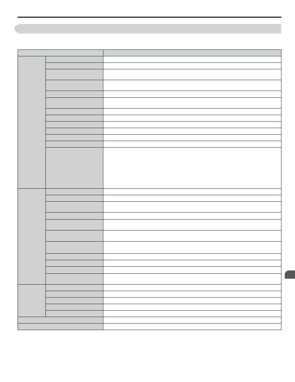
A.2 Drive Specifications
Note:
1. Perform rotational Auto-Tuning to obtain the performance specifications given below.
2. For optimum performance life of the drive, install the drive in an environment that meets the required specifications.
Item
Specification
Control
Character-
istics
Control Method
V/f Control (V/f)
Frequency Control Range
0.01 to 400 Hz
Frequency Accuracy
(Temperature Fluctuation)
Digital input: within ±0.01% of the max output frequency (-10 to +40 °C)
Analog input: within ±0.1% of the max output frequency (25 °C ±10 °C)
Frequency Setting Resolution Digital inputs: 0.01 Hz
Analog inputs: 1/2048 of the maximum output frequency setting (11 bit plus sign)
Output Frequency Resolution 0.001 Hz
Frequency Setting Signal
Main speed frequency reference: DC -10 to +10 V (20 kΩ), DC 0 to +10 V (20 kΩ),
4 to 20 mA (250 Ω), 0 to 20 mA (250 Ω)
Starting Torque
150% at 3 Hz
Speed Control Range
1:40
Speed Control Accuracy
V/f: ±0.2 to 3% (25 °C ±10 °C)
Accel/Decel Time
0.0 to 6000.0 s (4 selectable combinations of independent acceleration and deceleration settings)
Braking Torque
Same value as overload tolerance in motoring or regeneration.
V/f Characteristics
User-selected programs and V/f preset patterns possible
Main Control Functions
Momentary Power Loss Ride-Thru, Speed Search, Overtorque/Undertorque Detection, 4 Step Speed
(max), Accel/Decel Switch, S-curve Accel/decel, 3-Wire Sequence, Auto-Tuning (Stationary for Line-
to-Line Resistance, Rotational for V/f Control), Cooling Fan on/off Switch, Slip Compensation, Torque
Compensation, Frequency Jump, Upper/lower Limits for Frequency Reference, DC Injection Braking
at Start and Stop, Overexcitation Braking, PID Control (with sleep function), Energy Saving Control,
APOGEE FLN Comm. (RS-422/RS-485 4.8 kbps), BACnet Comm. (RS-485 max. 76.8 kbps),
MEMOBUS/Modbus Comm. (RS-422/RS-485 max, 115.2 kbps), Metasys N2 Comm. (RS-422/RS-485
9.6 kbps), Fault Restart, Application Presets, Overexcitation Deceleration, Sequence Timer Operation,
Secondary PI Control, Bypass Operation, HOA Keypad, Dynamic Noise Control
Protection
Functions
Power Supply Regeneration Available
Motor Protection
Thermal overload relay
Momentary Overcurrent
Protection
Drive stops when output current reaches about 200% of the rated current
Overload Protection
Drive stops after 60 s at 120% of rated output current
<1>
Overvoltage Protection
208 V: Stops when input voltage exceeds approx. 315 V
480 V: Stops when input voltage exceeds approx. 630 V
Undervoltage Protection
208 V: Stops when input voltage falls below approx. 150 V
480 V: Stops when input voltage falls below approx. 300 V
Momentary Power Loss
Ride-Thru
Immediately stop after 2 ms or longer power loss
<2>
Continuous operation during power loss than 2 s (standard)
<3>
Heatsink Overheat Protection Thermistor
Stall Prevention
Stall Prevention is available during acceleration, deceleration, and during run.
Ground Protection
Electronic circuit protection
<4>
Charge LED of Capacitor for
Control Power Supply
Remains lit until control power supply voltage falls below 50 V
Environment
Area of Use
Indoors
Ambient Temperature
IP20/NEMA Type 1 enclosure: -10 °C to +40 °C (14 °F to 104 °F)
Humidity
95 RH% or less (no condensation)
Storage Temperature
-20 °C to +60 °C (short-term temperature during transportation)
Altitude
Up to 1000 meters without derating, up to 3000 m with output current and voltage derating.
Standard
UL508A
Protection Design
IP20/NEMA Type 1 enclosure
<1> Overload protection may be triggered when operating with 150% of the rated output current if the output frequency is less than 6 Hz.
<2> Actual specifications may vary depending on motor characteristics.
<3> Use a separate Momentary Power Loss Ride-Thru Unit if the application needs to continue running for up to 2 s during momentary power loss.
<4> Ground protection cannot be provided when the impedance of the ground fault path is too low, or when the drive is powered up while a ground
fault is present at the output.
A.2 Drive Specifications
YASKAWA SIEP YAIZ1D 01A Z1000U HVAC MATRIX Drive Bypass Technical Manual
303
A
Specifications