Switches and jumpers on the terminal board, 5 control circuit wiring – Yaskawa Z1000U HVAC Matrix Bypass User Manual
Page 104
Advertising
u
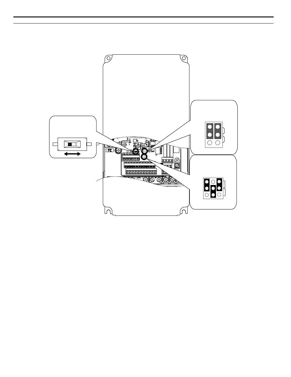
Switches and Jumpers on the Terminal Board
shows the location of these switches.
Refer to Bypass and Drive Control I/O Connections on page 105
instructions.
E(G) IG R+ R- S+ S-
S1 S2 S3 S4 S5 S6 S7 S8 SN SC SP
V+ AC A1 A2 A3 FM AM AC
24V
RP AC
M1 M2 M3 M4
MD ME MF
MA MB MC
Selection
Jumper S5
Terminal AM/FM Signal
DIP Switch S2
RS-422/RS-485
Termination Resistor
Off
On
Jumper S1
A1/A2/A3 Volt/Curr.
Selection
V
I
A1 A2 A3
V
AM
FM
I
Figure 3.34 Locations of Jumpers and Switches on the Terminal Board
3.5 Control Circuit Wiring
104
YASKAWA SIEP YAIZ1D 01A Z1000U HVAC MATRIX Drive Bypass Technical Manual
Advertising