U1 - 10, U1 - 12 – Yaskawa Z1000U HVAC Matrix Bypass User Manual
Page 343
No.
(Addr.
Hex)
Name
LCD Display
Description
Analog
Output Level
Unit
U1-03
(0042)
Output Current
Output Current
Displays the output current.
10 V: Drive
rated current
<1>
<2>
U1-04
(0043)
Control Method
Control Method
0: V/f Control
No signal output
available
–
U1-06
(0045)
Output Voltage
Reference
Output Voltage
Displays the output voltage.
10 V: 200 Vrms
<3>
0.1 Vac
U1-07
(0046)
DC Bus Voltage
DC Bus Voltage
Displays the DC bus voltage.
10 V: 400 V
<3>
1 Vdc
U1-08
(0047)
Output Power
Output kWatts
Displays the output power (this value is calculated internally).
10 V: Drive
rated power
(kW)
<4>
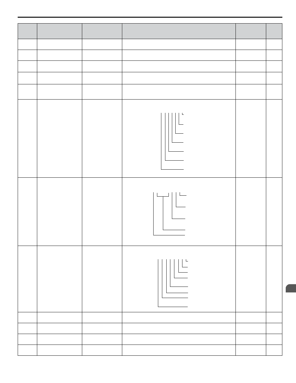
U1-10
(0049)
Input Terminal Status
Input Term Sts
Displays the input terminal status.
U1 - 10=
00000000
Digital input 1
(terminal S1 enabled)
Digital input 2
(terminal S2 enabled)
Digital input 3
(terminal S3 enabled)
Digital input 4
(terminal S4 enabled)
Digital input 5
(terminal S5 enabled)
Digital input 6
(terminal S6 enabled)
Digital input 7
(terminal S7 enabled)
1
1
1
1
1
1
1
No signal output
available
–
U1-11
(004A) Output Terminal Status Output Term Sts
Displays the output terminal status.
U1 - 11=
00000000
Multi-Function
Digital Output
(terminal MD-ME-MF)
Digital Output
(terminal M1-M2)
Digital Output
(terminal M3-M4)
Multi-Function
Multi-Function
Not Used
Fault Relay
(terminal MA-MC closed
MA/MB-MC open)
1
1
1
1
0
No signal output
available
–
U1-12
(004B) Drive Status
Int Ctl Sts 1
Verifies the drive operation status.
U1 - 12=
00000000
During run
During zero-speed
During REV
During fault reset
signal input
During speed agree
Drive ready
During alarm
detection
During fault detection
1
1
1
1
1
1
1
1
No signal output
available
–
U1-13
(004E) Terminal A1 Input Level Term A1 Level
Displays the signal level to analog input terminal A1.
10 V: 100%
0.1%
U1-14
(004F) Terminal A2 Input Level Term A2 Level
Displays the signal level to analog input terminal A2.
10 V: 100%
0.1%
U1-15
(0050)
Terminal A3 Input Level Term A3 Level
Displays the signal level to analog input terminal A3.
10 V: 100%
(-10 to +10 V)
0.1%
U1-16
(0053)
Output Frequency after
Soft Starter
SFS Output
Displays output frequency with ramp time and S-curves. Units
determined by o1-03.
10 V: Max
frequency
0.01 Hz
B.14 U: Monitors
YASKAWA SIEP YAIZ1D 01A Z1000U HVAC MATRIX Drive Bypass Technical Manual
343
B
Parameter List